Phase Change Material (PCM) in HVAC System CFD Simulation
$140.00 $70.00 Student Discount
- This study investigates the thermal performance of an HVAC system with Phase Change Materials (PCMs) using ANSYS Fluent.
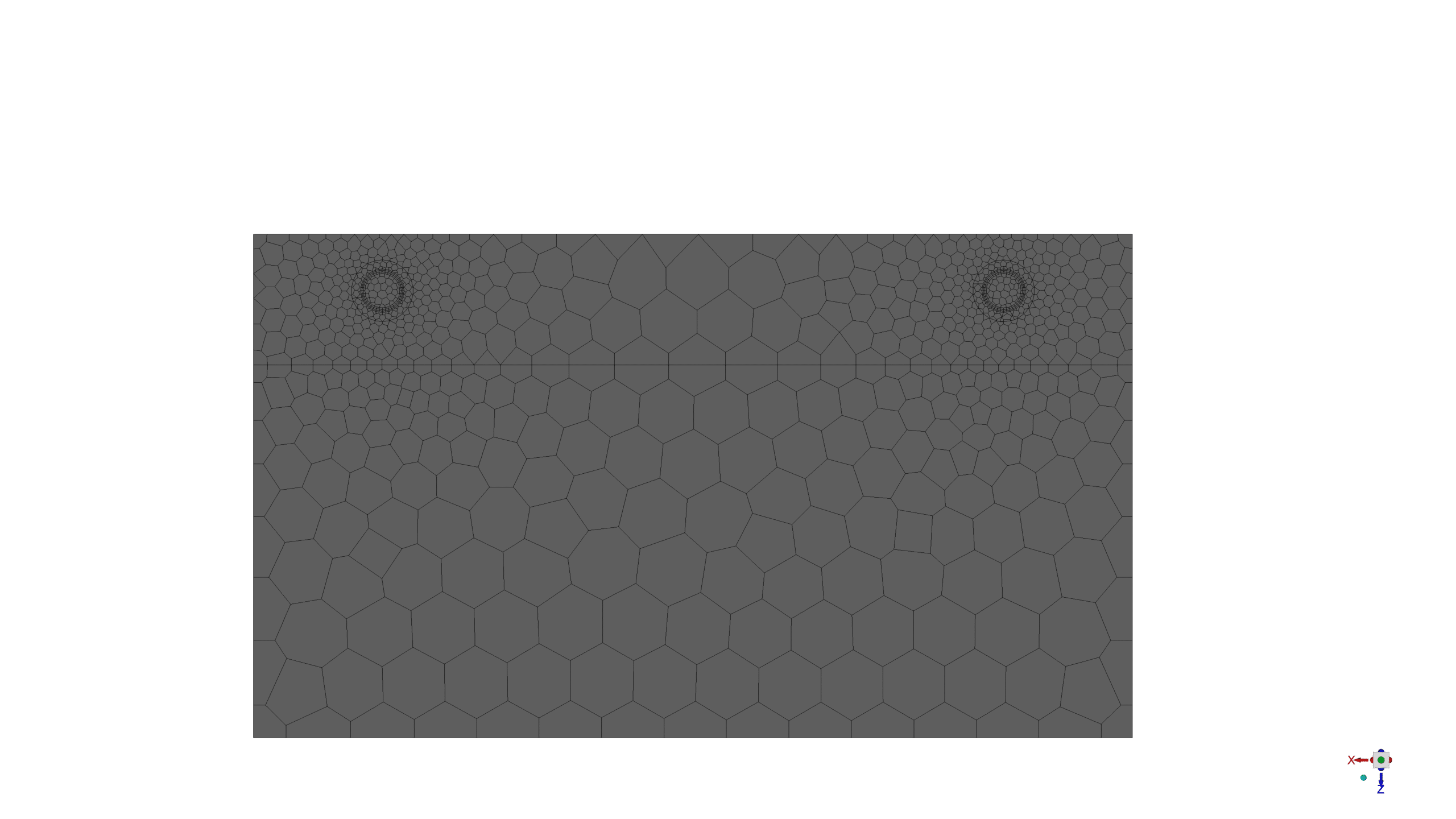
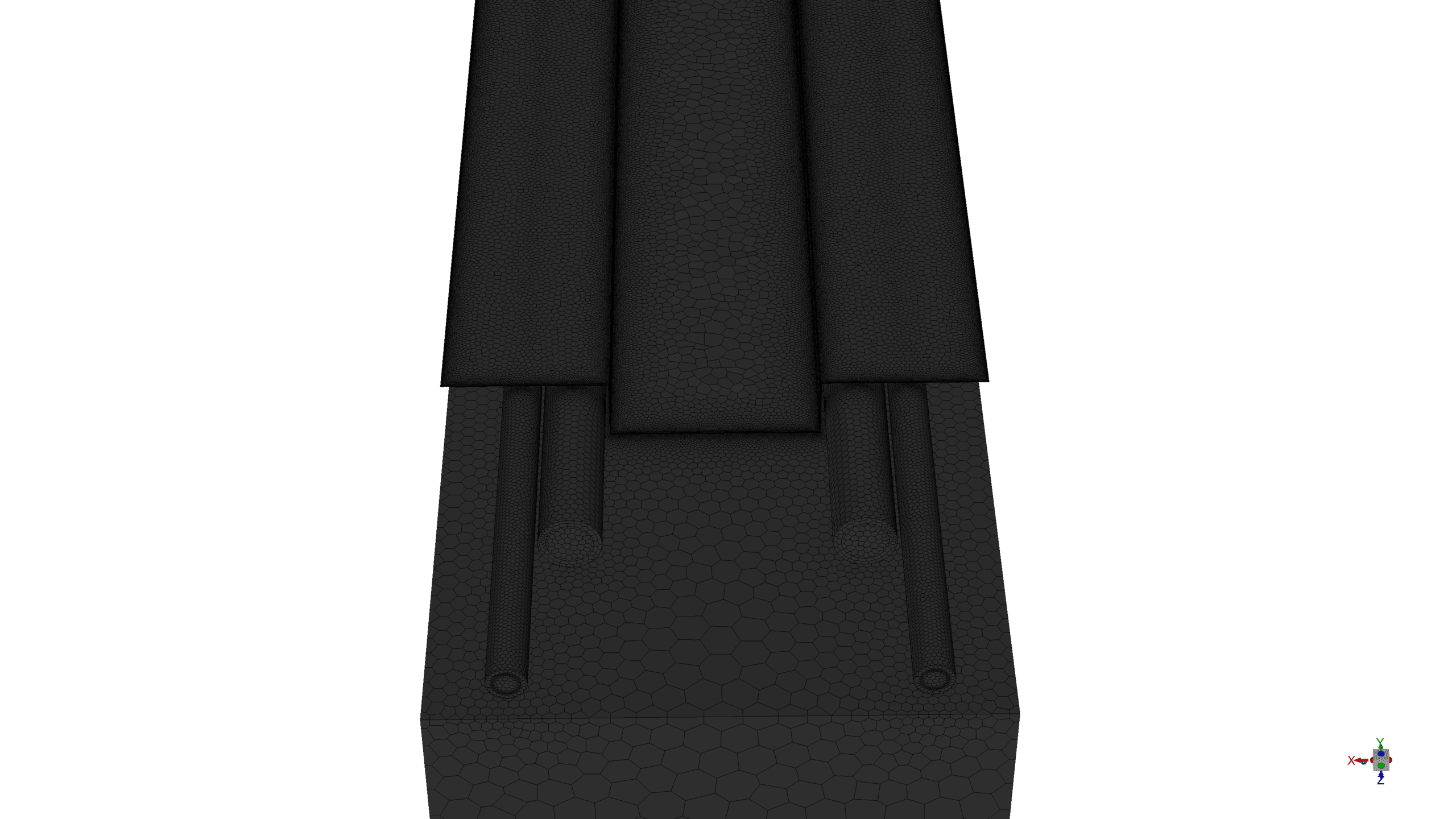
- The geometry, representing a U-shape pipe system with PCM-filled pipes, is designed in ANSYS SpaceClaim and meshed using ANSYS Meshing, resulting in 6,204,324 polyhedra elements.
- The simulation is conducted as a transient analysis over 24 hours.
- The RNG k-ε turbulence model is employed, and the Solidification and Melting model is activated with a Mushy Zone Parameter of 100,000.
- The energy equation is enabled to accurately model heat transfer.
To Order Your Project or benefit from a CFD consultation, contact our experts via email (info@mr-cfd.com), online support tab, or WhatsApp at +44 7443 197273.
There are some Free Products to check our service quality.
If you want the training video in another language instead of English, ask it via info@mr-cfd.com after you buy the product.
Description
Phase Change Material (PCM) in HVAC System, CFD Simulation using ANSYS Fluent
Introduction
This study investigates the thermal performance of a heating, ventilation, and air conditioning (HVAC) system incorporating Phase Change Materials (PCMs) using Computational Fluid Dynamics (CFD) analysis. The simulation aims to understand the heat transfer dynamics, phase change behaviour, and overall energy efficiency of the system over a 24-hour period. By employing advanced models for turbulence, energy transfer, and phase change, this research provides valuable insights into the complex interplay of fluid dynamics and thermal physics in PCM-enhanced HVAC systems.
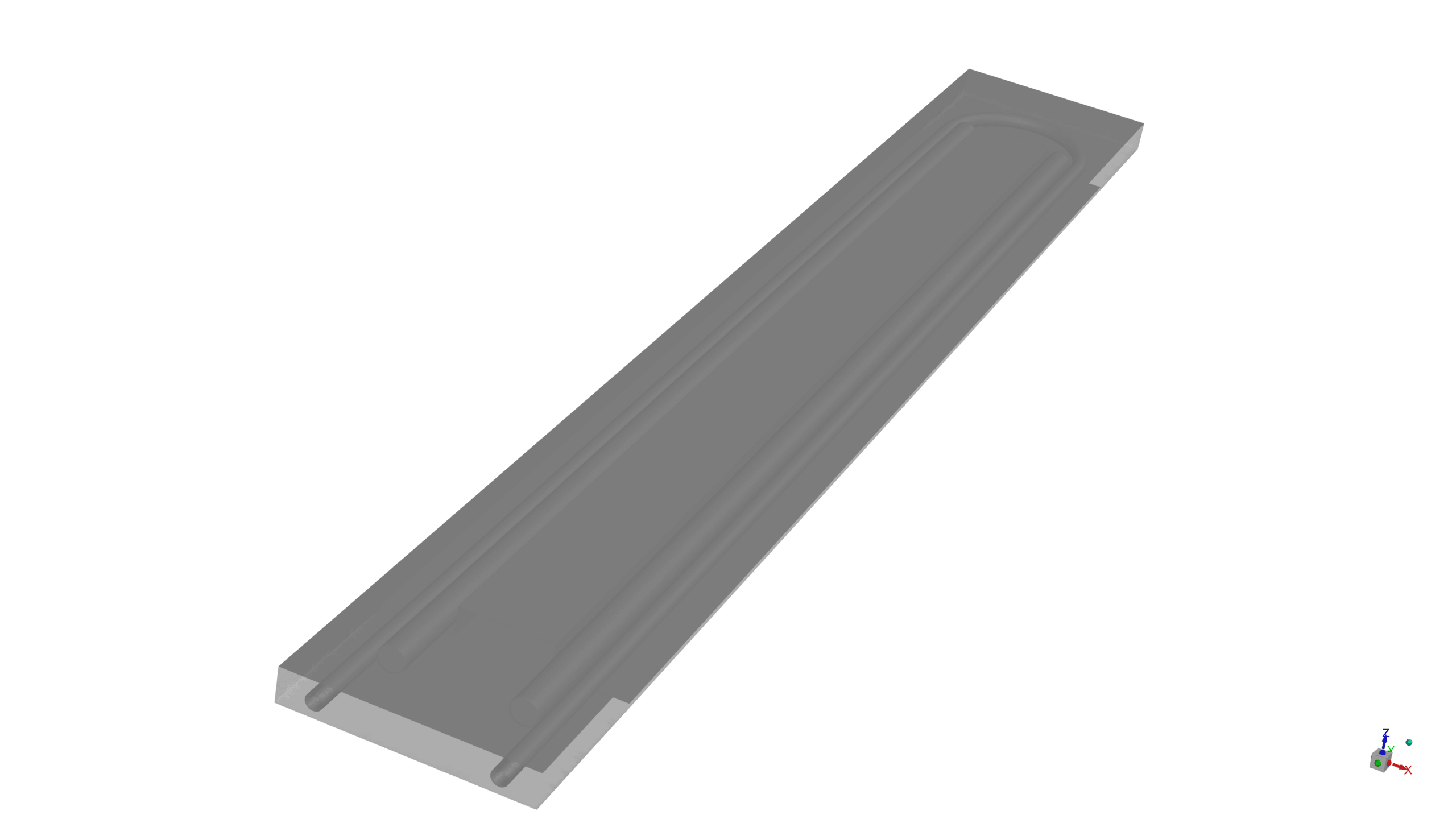
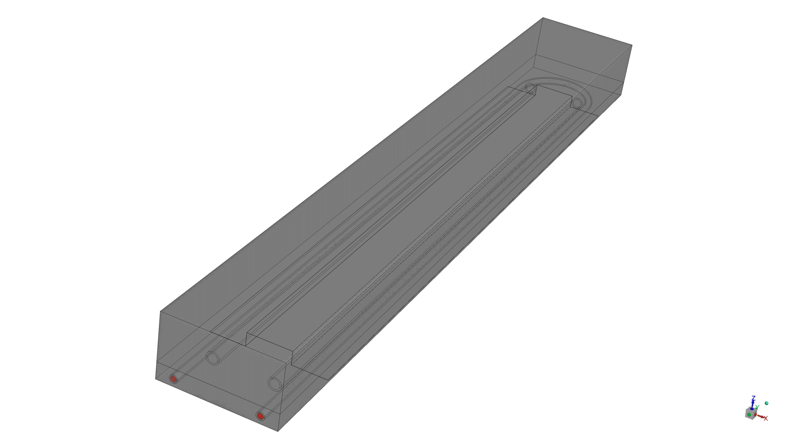
The CFD simulations were conducted using ANSYS Fluent software. The geometry was designed in ANSYS SpaceClaim to represent a U-shape pipe system with water flow and two separate PCM-filled pipes, surrounded by encapsulated microcapsules, covered with plaster, and an insulation zone above them. ANSYS Meshing was used to generate a high-quality mesh consisting of 6,204,324 polyhedra elements, ensuring accurate results.
Methodology
The simulation was set up as a transient analysis over a 24-hour period to capture the full cycle of PCM phase change and its impact on system performance.
The RNG k-ε model was utilized for turbulence modeling, accounting for the complex flow patterns within the U-bend and straight sections of the pipe.
The energy equation was enabled to accurately model heat transfer within the system, which is crucial for capturing the thermal behaviour of the PCM and surrounding materials.
The Solidification and Melting model was activated with a Mushy Zone Parameter of 100,000 to simulate the PCM’s phase change behaviour accurately.
Results
The CFD simulation provided comprehensive insights into the thermal and fluid dynamic behaviour of the PCM-enhanced HVAC system over the 24-hour period:
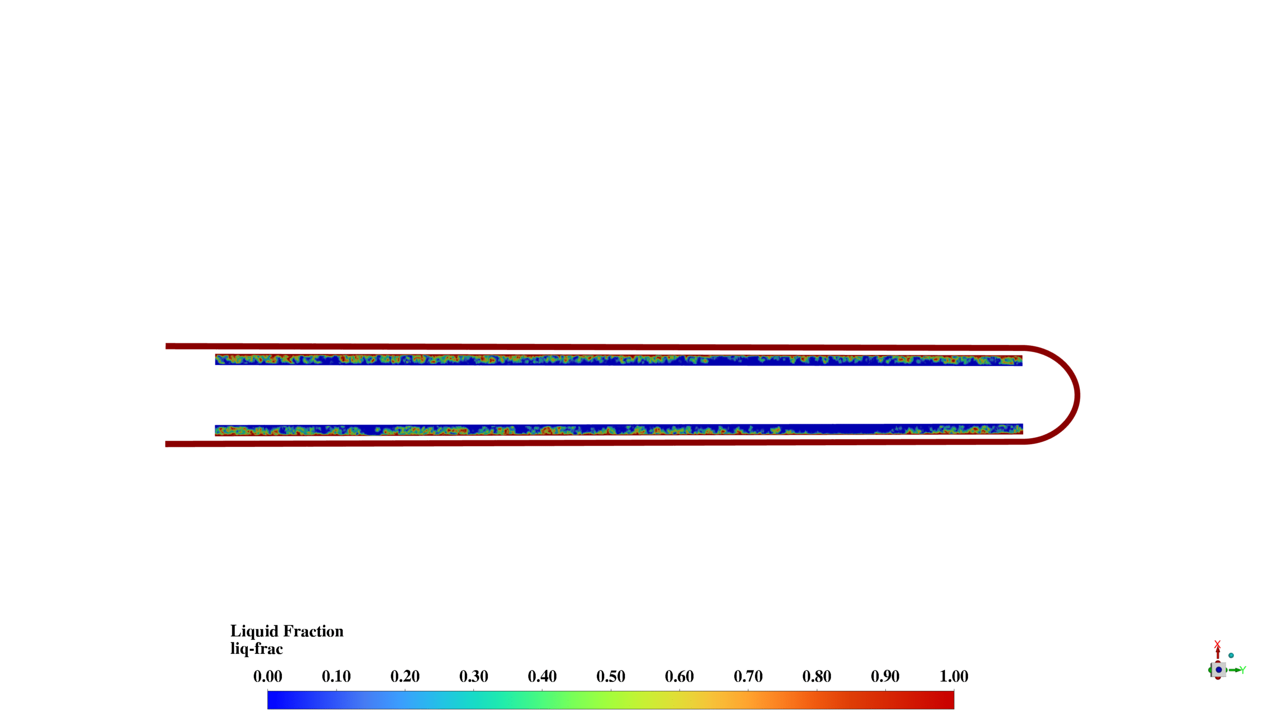
The volume average static temperature in the PCM1 and PCM2 zones reached 316.759 K, approaching but not quite reaching the solidus temperature of 317.2 K. This indicates that the PCM has absorbed a significant amount of heat but has not fully melted. The liquid fraction in the PCM pipes was 0.316, confirming partial melting and demonstrating the PCM’s effectiveness in absorbing latent heat.
The plaster’s volume average static temperature was 310.774 K, while the capsulation zones reached 316.366 K. This temperature gradient illustrates the system’s ability to distribute heat effectively through different layers, with the capsulation zones acting as an efficient thermal buffer between the PCM and the plaster.
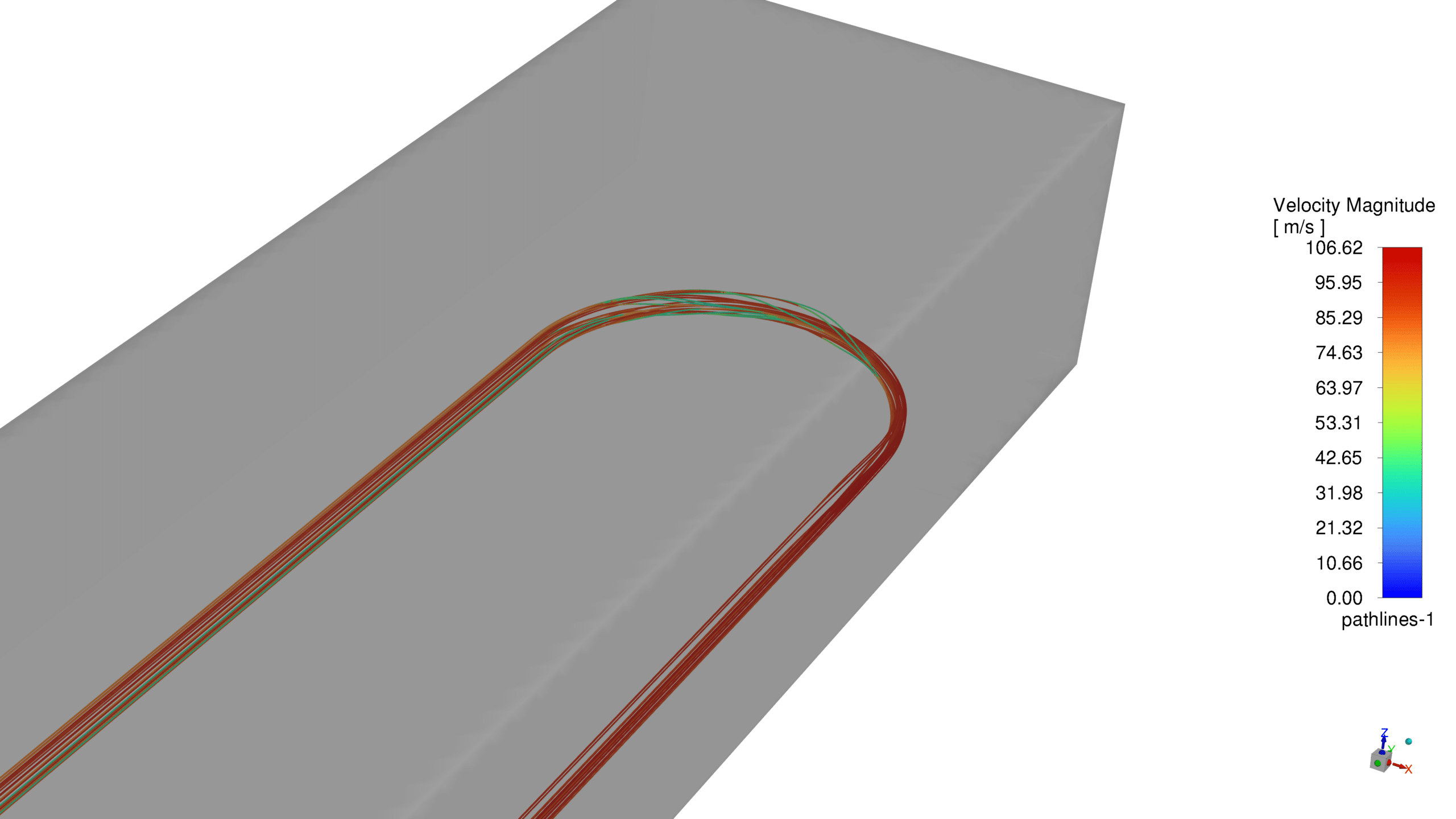
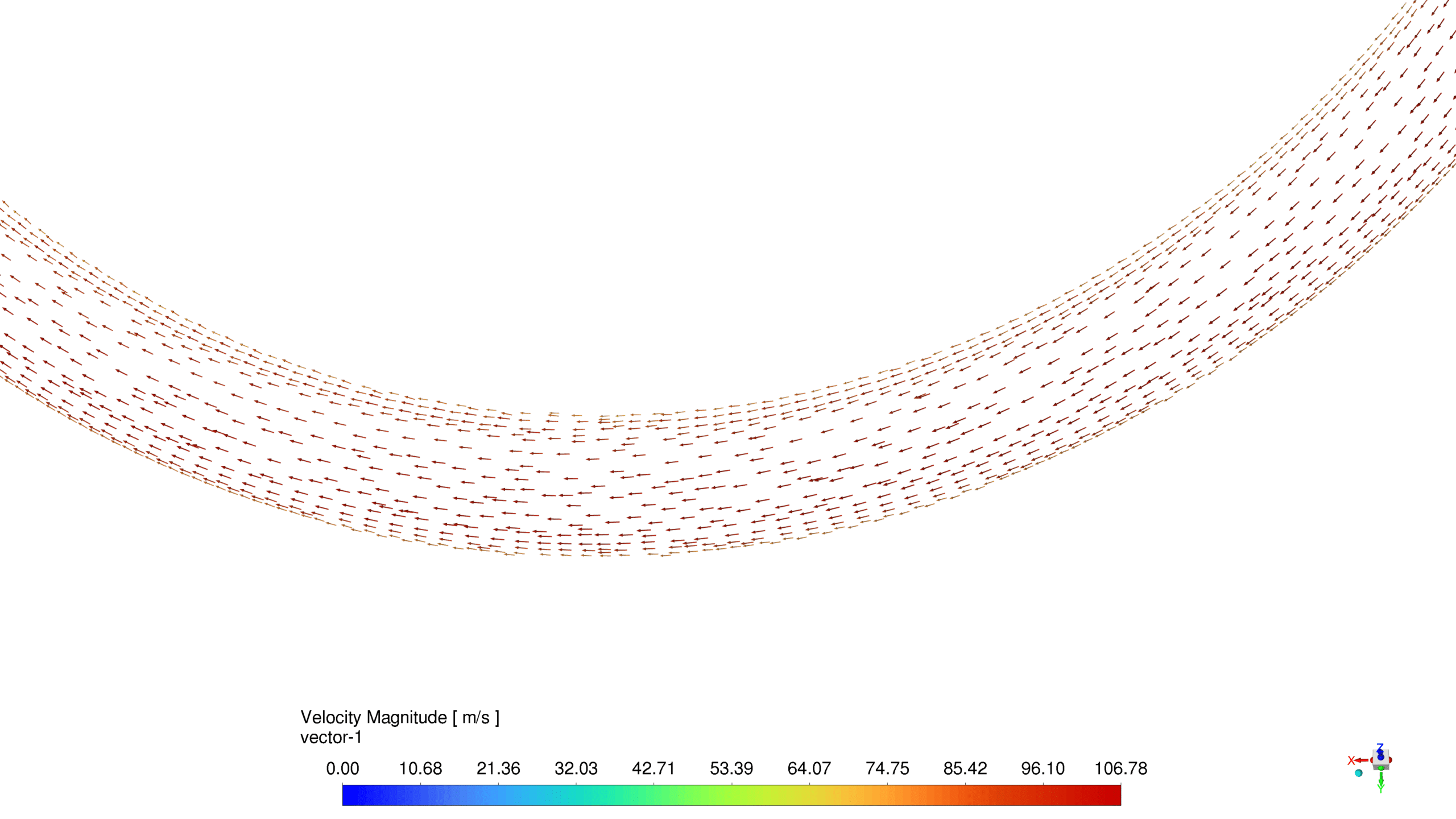
Furthermore, the velocity magnitude contours and vector plot reveal complex flow patterns, particularly in the U-bend region. The maximum velocity observed was 106.62 m/s, occurring in the U-bend. This high velocity suggests a potential for enhanced heat transfer due to turbulence but also indicates the need for careful consideration of pressure drop and pumping requirements in system design.
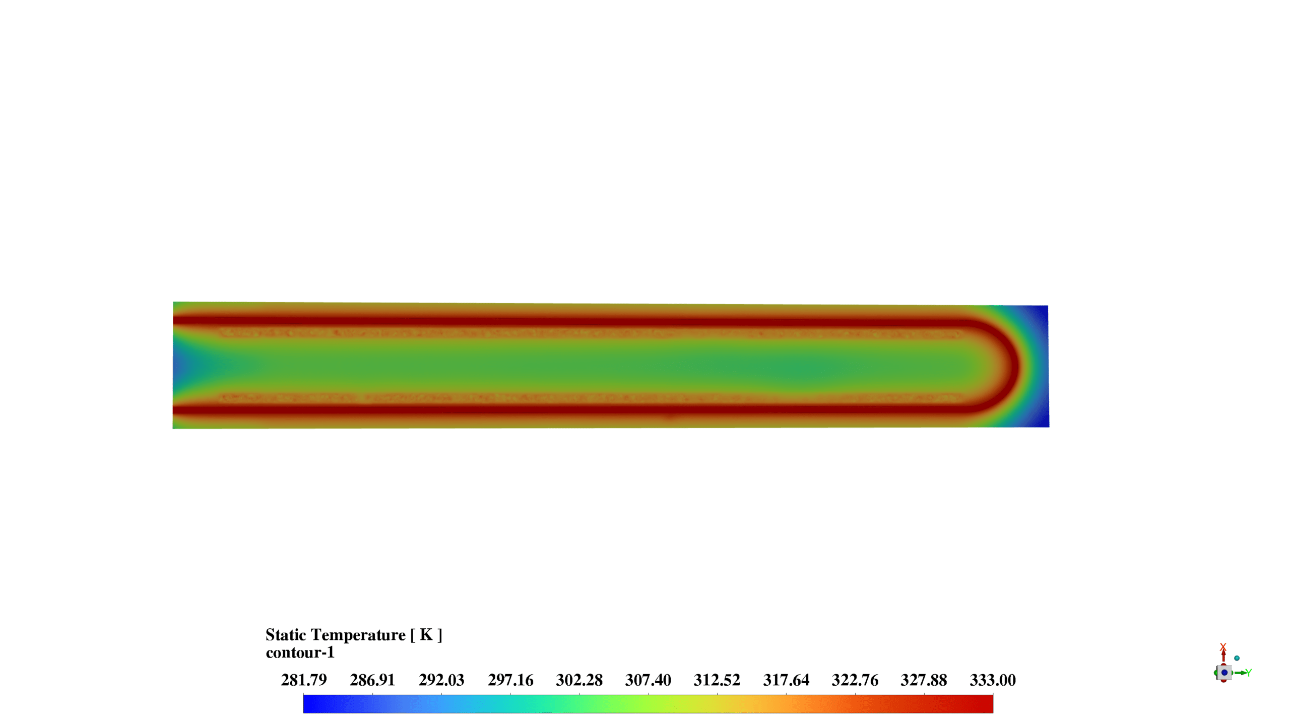
The static temperature contours show a gradient from 300 K to 333 K across the system. The highest temperatures are observed near the inlet and along the water flow path, driving the heat transfer process and the phase change of the PCM.
The liquid fraction contours indicate partial melting of the PCM, with higher liquid fractions observed near the water pipes. This non-uniform melting pattern suggests that heat transfer from the water to the PCM is most effective near the pipe walls, with the potential for optimization in PCM distribution or pipe design.
The simulation results demonstrate the complex interplay between fluid flow, heat transfer, and phase change in the PCM-enhanced HVAC system. The partial melting of the PCM (liquid fraction of 0.316) indicates that the system has not reached its full heat storage capacity within the 24-hour period, suggesting potential for further optimization of PCM properties or system design to maximize energy storage and release cycles.
The high velocities observed in the U-bend region highlight the importance of considering fluid dynamics in system design, as these could impact both heat transfer efficiency and overall system performance. The temperature gradients observed throughout the system illustrate the effective distribution of thermal energy, with the PCM and capsulation zones playing crucial roles in heat absorption and storage.


Reviews
There are no reviews yet.