Pin-Fin Heat Exchanger Thermal Management
$80.00 $40.00 Student Discount
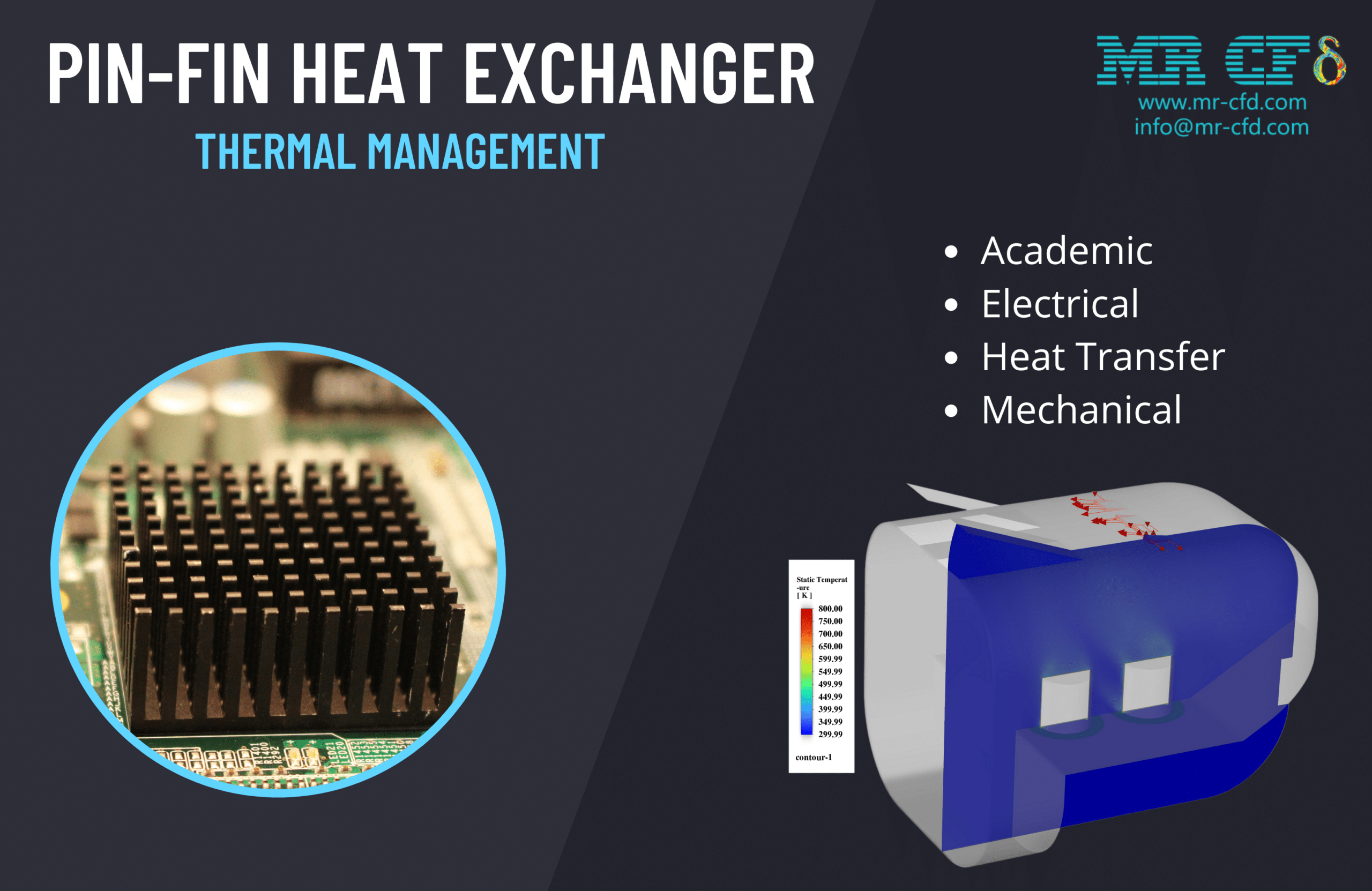
- This study investigates the thermal and fluid dynamics behavior of a pin-fin heat exchanger using CFD simulation.
- The geometry of the pin-fin heat exchanger was created using ANSYS Design Modeler.
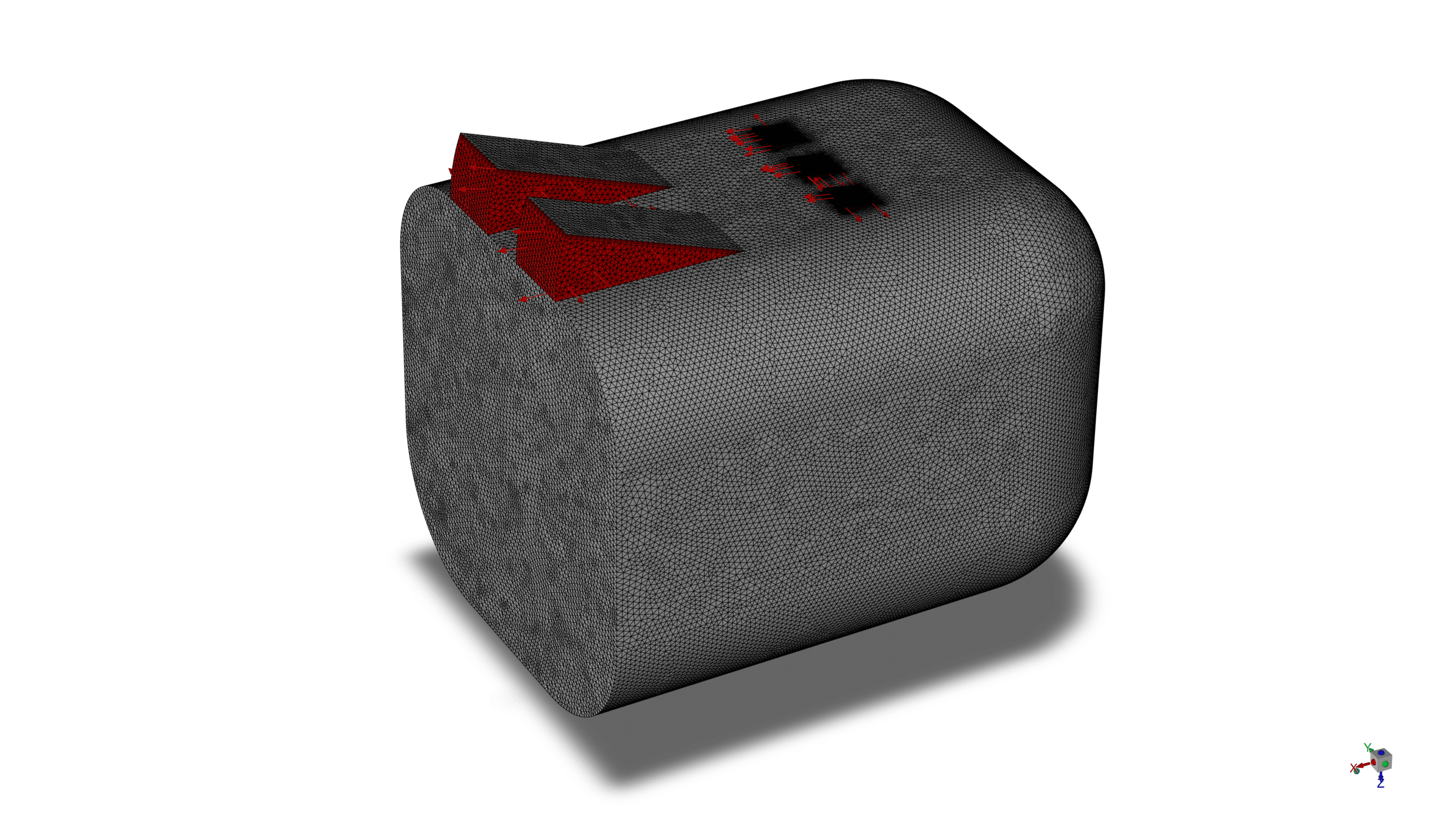
- The computational domain was then discretized using ANSYS Meshing, resulting in 1,679,530 elements.
- The pin wall temperature was set to a constant 800 K to simulate a high-temperature heat source
To Order Your Project or benefit from a CFD consultation, contact our experts via email (info@mr-cfd.com), online support tab, or WhatsApp at +44 7443 197273.
There are some Free Products to check our service quality.
If you want the training video in another language instead of English, ask it via info@mr-cfd.com after you buy the product.
Description
Introduction
This study investigates the thermal and fluid dynamics behavior of a pin-fin heat exchanger using Computational Fluid Dynamics (CFD) simulation. Pin-fin heat exchangers are crucial in various engineering applications, including electronics cooling, automotive systems, and industrial processes. The simulation aims to analyze the flow patterns, temperature distribution, and heat transfer characteristics within the heat exchanger, providing insights for optimizing its design and performance.
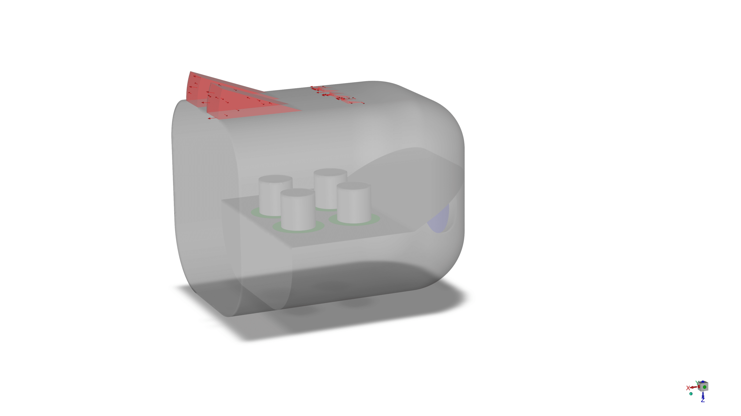
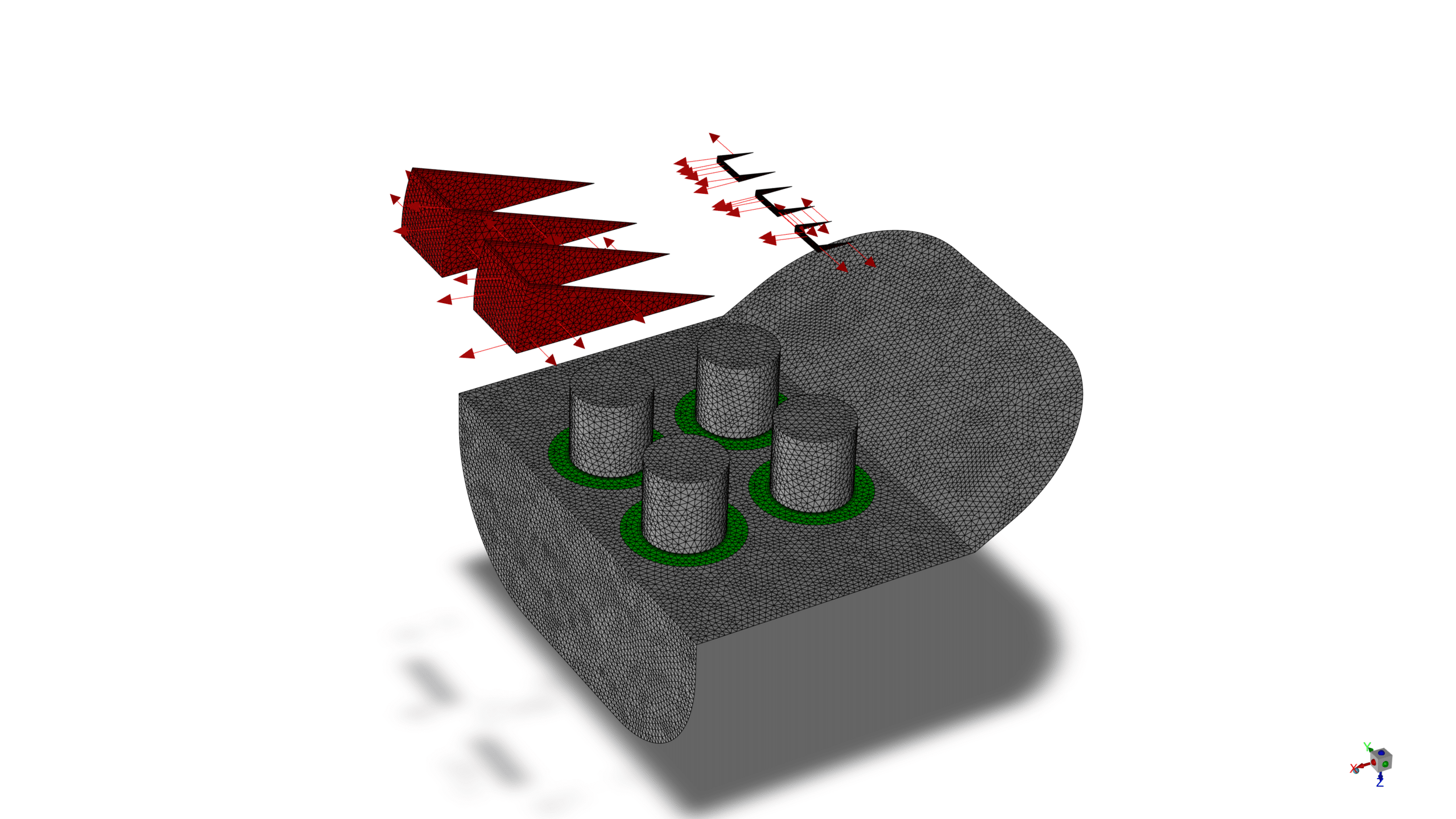
The simulation was conducted using ANSYS Fluent, a powerful CFD software package. The geometry of the pin-fin heat exchanger was created using ANSYS Design Modeler, featuring an inlet on the right side, multiple cylindrical pins, and several outlets on the upper surface of Pin-Fin. The computational domain was then discretized using ANSYS Meshing, resulting in 1,679,530 elements, providing a balance between computational efficiency and solution accuracy.
Methodology
The simulation setup included a pressure-based solver in a steady-state condition, allowing for a time-independent analysis of the flow.
For turbulence modeling, the Realizable k-epsilon model with standard wall function was selected, providing a robust approach for capturing the complex flow patterns around the pins and within the heat exchanger.
The geometry was created in ANSYS Design Modeler, featuring an inlet on the right side, multiple cylindrical pins as heat sources, and several outlets on the upper surface.
ANSYS Meshing was used to discretize the computational domain, resulting in a total of 1,679,530 elements, ensuring adequate resolution for capturing the flow and thermal features.
The pin wall temperature was set to a constant 800 K to simulate a high-temperature heat source. The outlet configuration consisted of a variable outlet (the largest) and several fixed outlets (smaller).
Results
and Discussion The mesh visualization demonstrates a well-structured grid, with refinement near the pins and walls to capture the complex flow features accurately.
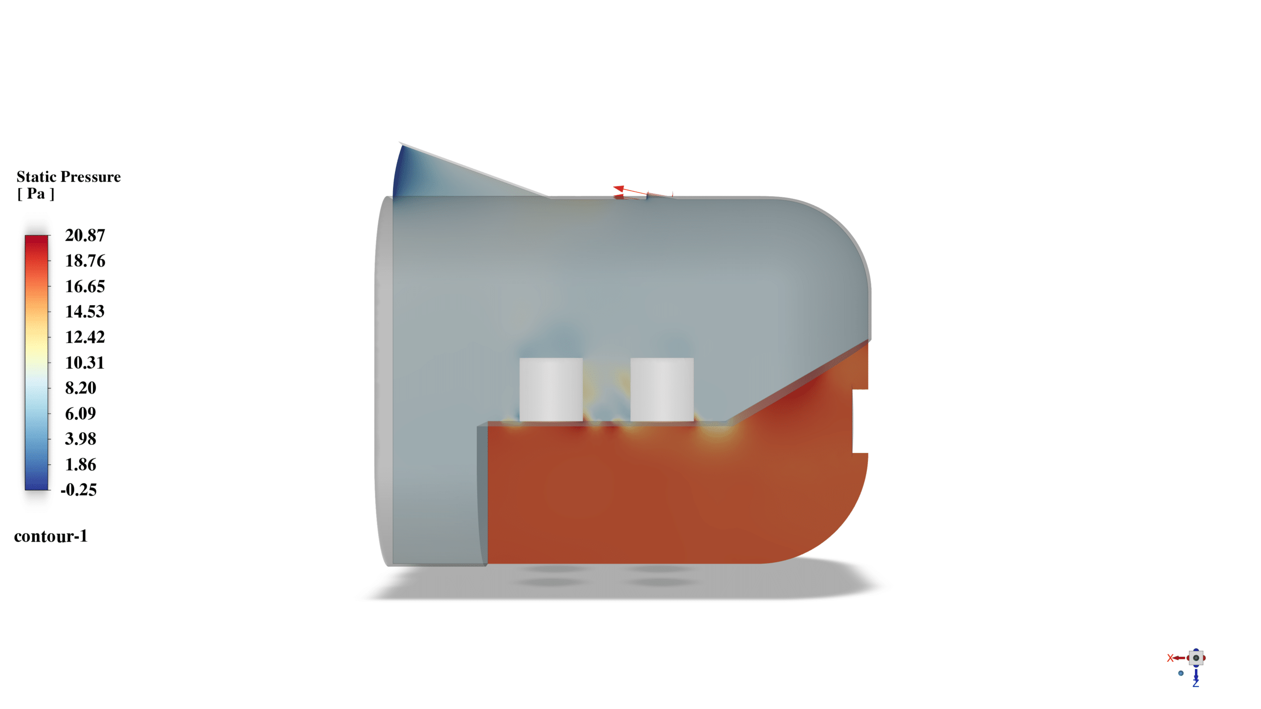
The static pressure contour reveals a pressure gradient from the inlet to the outlets, driving the fluid flow through the device. Higher pressure regions are observed near the inlet and lower pressure areas near the outlets, consistent with the flow direction.
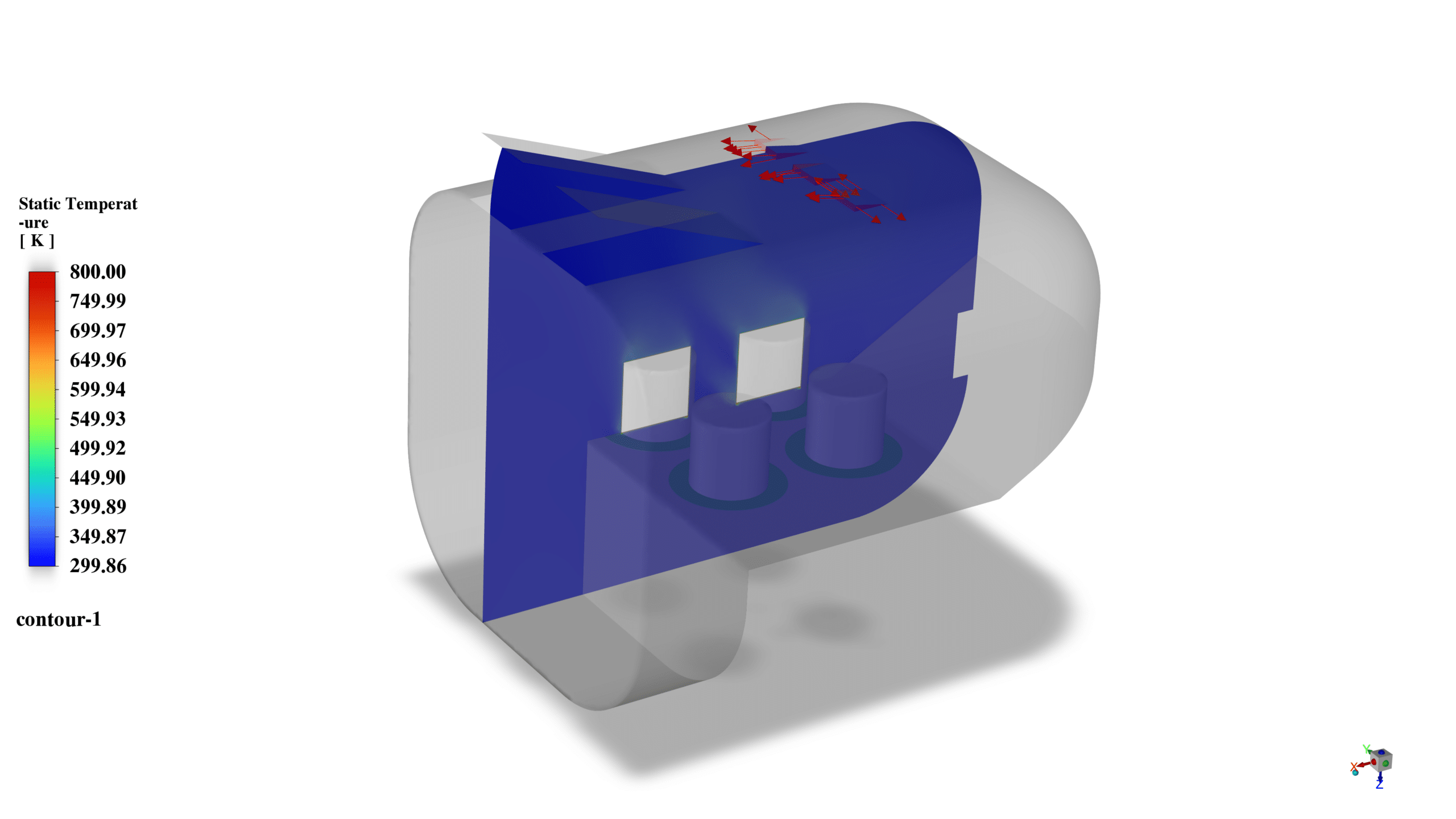
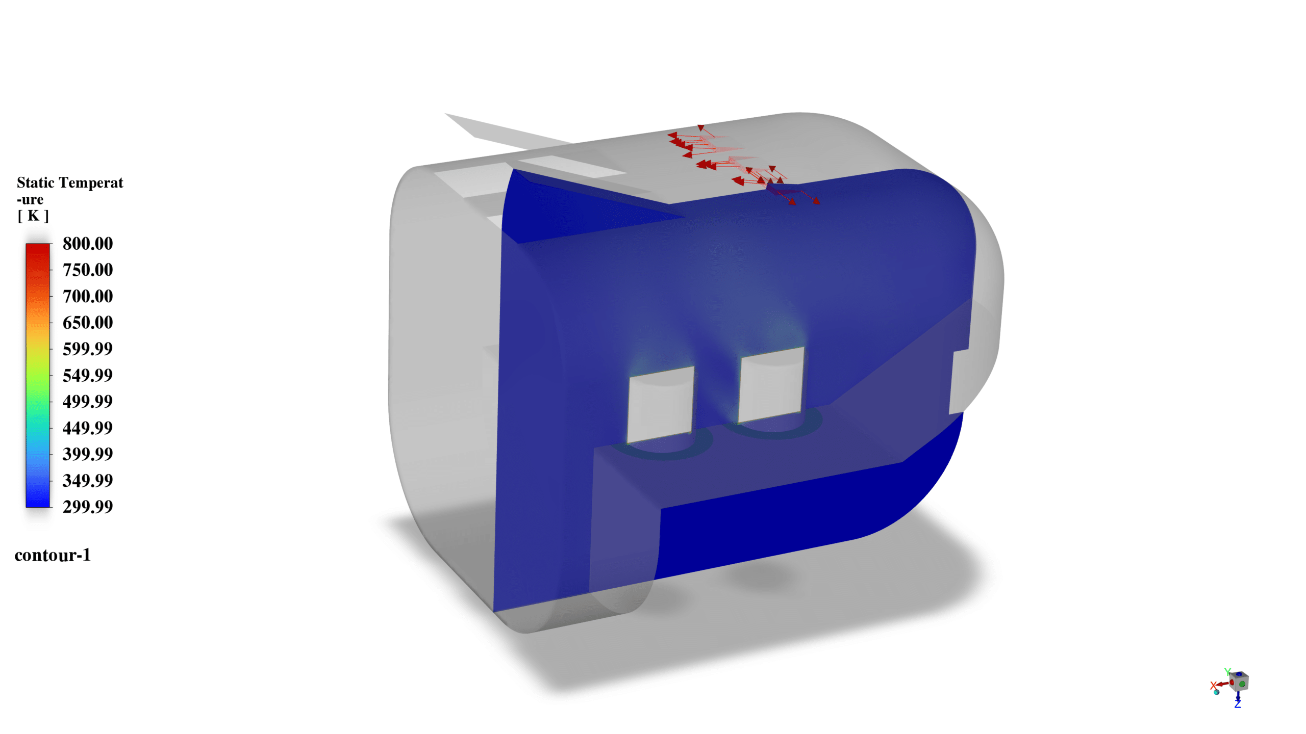
The temperature distribution plot shows a significant temperature gradient within the heat exchanger. The fluid enters at a lower temperature (around 300 K) and is heated as it passes over the hot pins (800 K). The temperature increases progressively from the inlet to the outlets, with the highest temperatures observed near the pin surfaces.
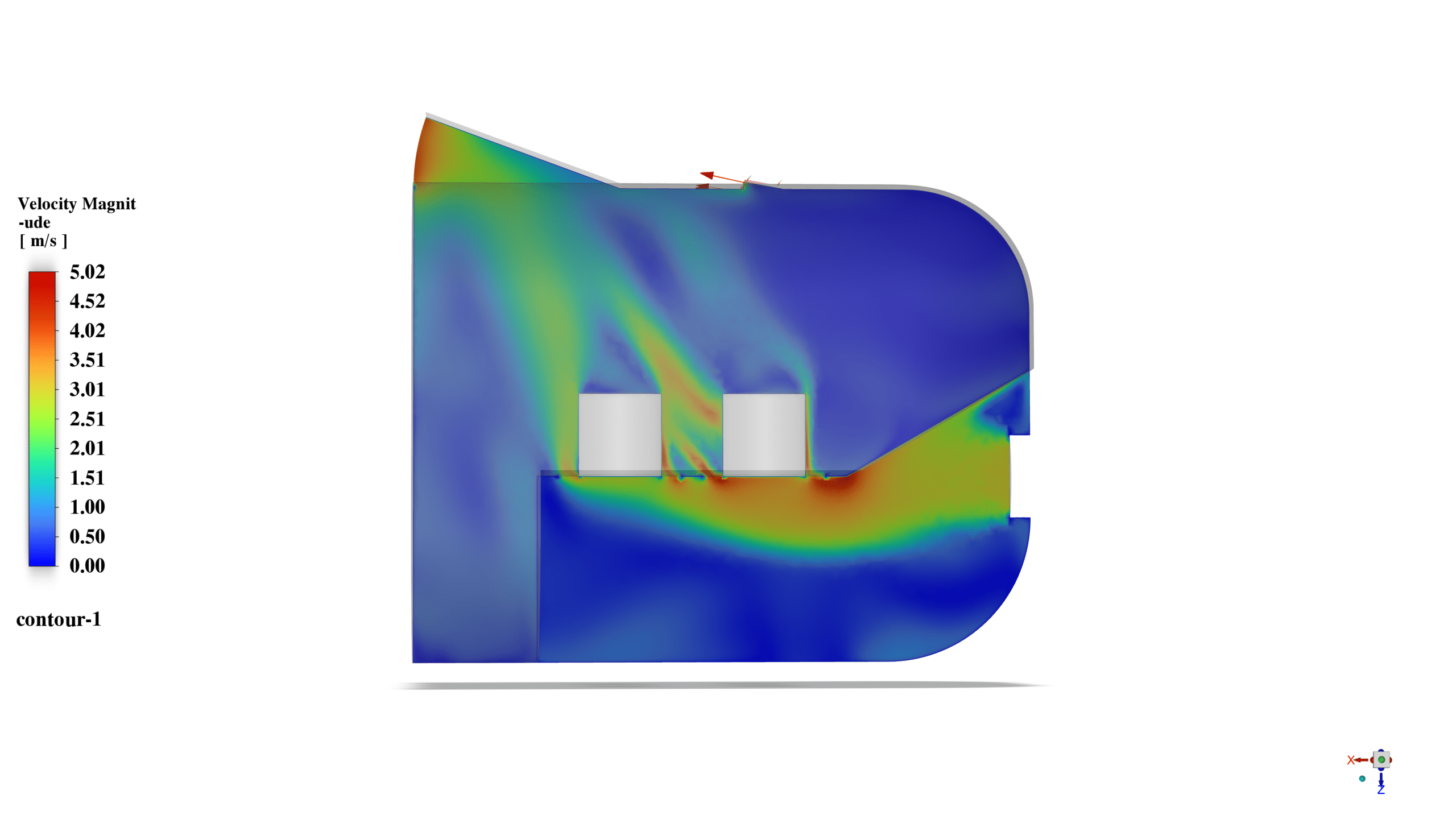
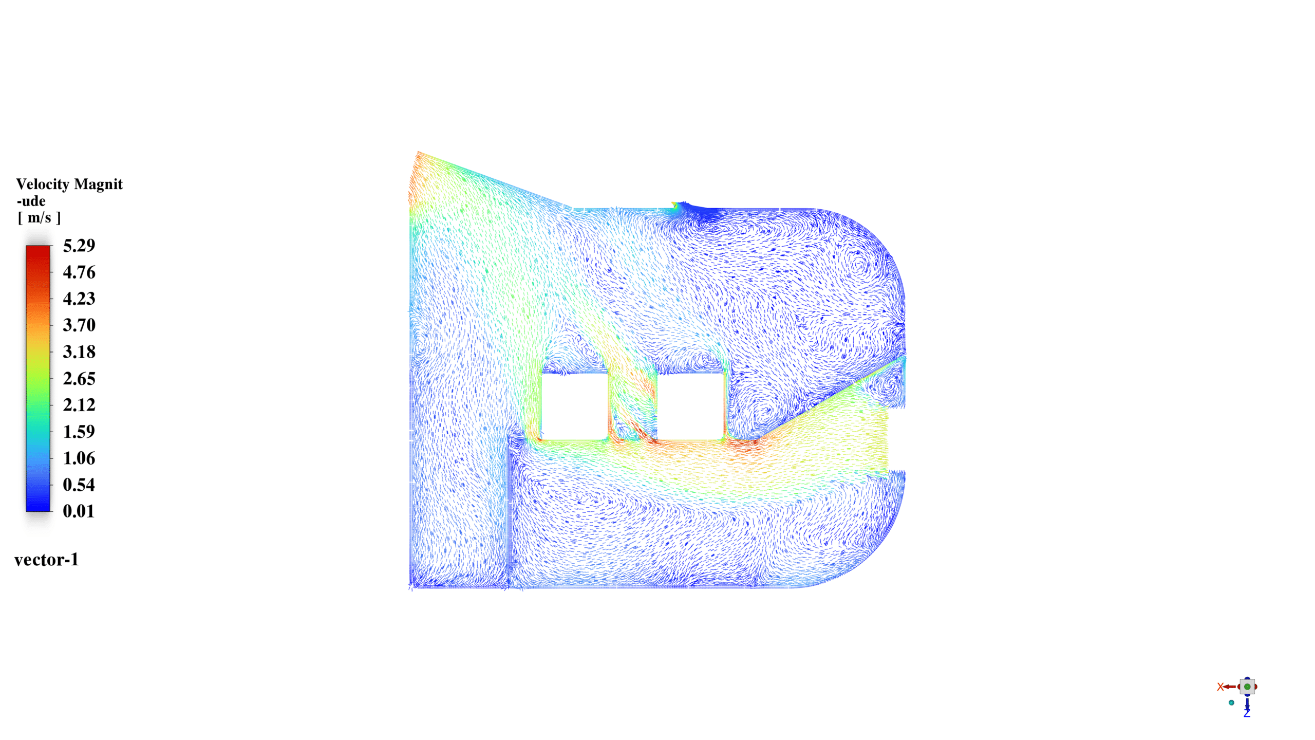
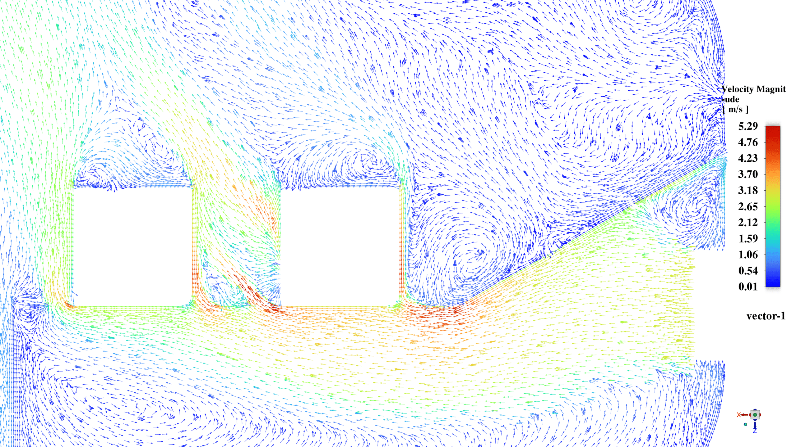
The velocity magnitude contour illustrates complex flow patterns within the heat exchanger. The maximum velocity reaches approximately 5.29 m/s, with higher velocities observed in the spaces between pins and near the outlets. Lower velocity regions are seen in the wake of the pins, indicating potential recirculation zones.
The vector plot and pathlines visualization reveal intricate flow structures, including vortices and recirculation zones around the pins. These flow features enhance mixing and heat transfer but also contribute to pressure drop across the device.
The area-weighted average static temperature at the outlets provides quantitative data on the heat exchanger’s performance:
- Fixed outlet: 319.8177 K
- Variable outlet: 312.8119 K
These results indicate that the fluid temperature increases by approximately 20 K and 13 K for the fixed and variable outlets, respectively, demonstrating the heat exchanger’s effectiveness in transferring heat from the pins to the fluid.
In conclusion, the CFD simulation successfully captured the thermal and fluid dynamics behavior of the pin-fin heat exchanger. The results demonstrate the device’s ability to transfer heat from the high-temperature pins to the working fluid, with complex flow patterns enhancing heat transfer efficiency. The study highlights the importance of pin arrangement, flow distribution, and outlet configuration in optimizing heat exchanger performance. Further studies could explore different pin geometries, arrangements, or working fluids to enhance thermal management capabilities.



Reviews
There are no reviews yet.