Pollution Ventilation in a Subway, CFD Simulation ANSYS Fluent Training
$160.00 $80.00 Student Discount
This simulation is about pollution in the subway via ANSYS Fluent software.
Click on Add To Cart and obtain the Geometry file, Mesh file, and a Comprehensive ANSYS Fluent Training Video.To Order Your Project or benefit from a CFD consultation, contact our experts via email (info@mr-cfd.com), online support tab, or WhatsApp at +44 7443 197273.
There are some Free Products to check our service quality.
If you want the training video in another language instead of English, ask it via info@mr-cfd.com after you buy the product.
Description
Pollution Ventilation in a Subway Description
This simulation is about Pollution Ventilation in a Subway via ANSYS Fluent software. In this project, the air conditioning system of subway stations has been studied.
The subway station is one of the busiest public places. Therefore, this environment is easily exposed to pollution. In this modeling, a polluting gas with a molecular weight of 77.5 kg/kmol and a specific heat capacity of 1100 j/kg.K is defined.
Subway doors are assumed to be sources of pollutants because they are a place for passengers. The subway air conditioning system is to be located on the ceiling of the subway station to transfer pollutants into the outside environment with its suction power. The pollutant gas enters the subway station at a velocity of 0.1 m/s and is transferred to the outside environment by vacuum pressure.
In this simulation, the species transport model is used. In this model, two species must be defined. Because there is airflow inside the station, then pollutant gas enters it. The species transport model solves each defined species’ transport equations.
Also, the exhaust fan boundary condition is used to define the suction in the output panels located on the ceiling of the subway station. In the exhaust fan, a pressure jump is defined in which the pollutant gas is sucked out of the environment. This pressure jump is equivalent to 1000,000 Pa.
Geometry & Mesh
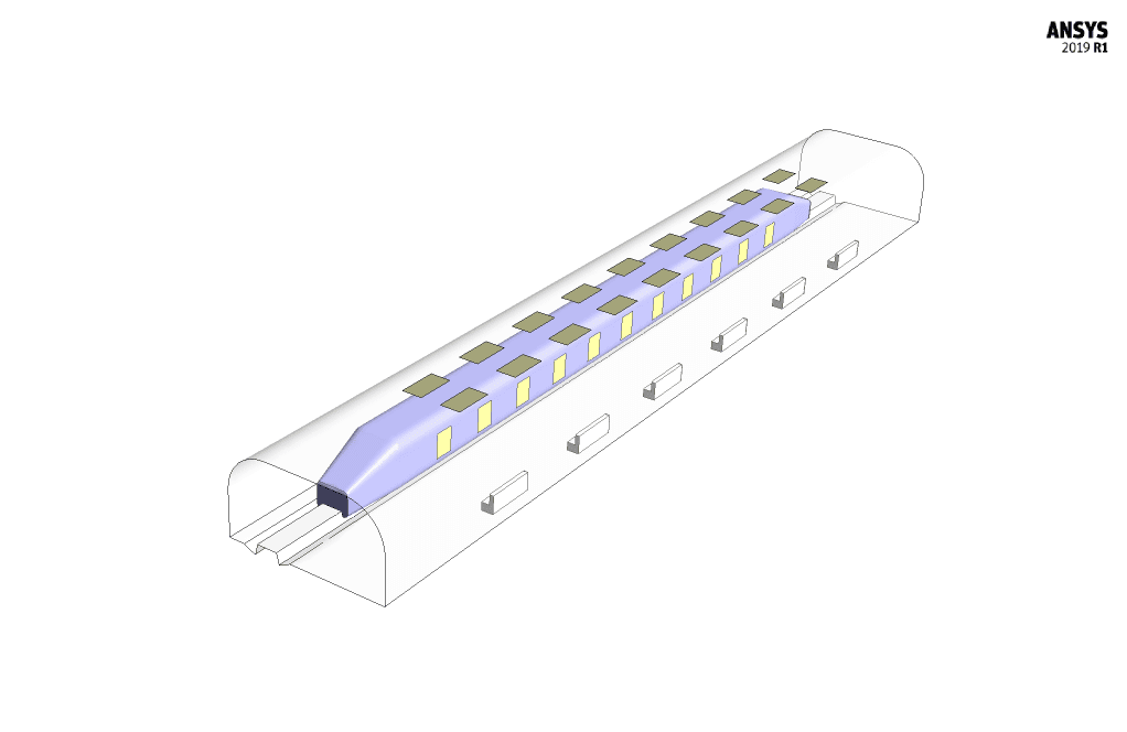
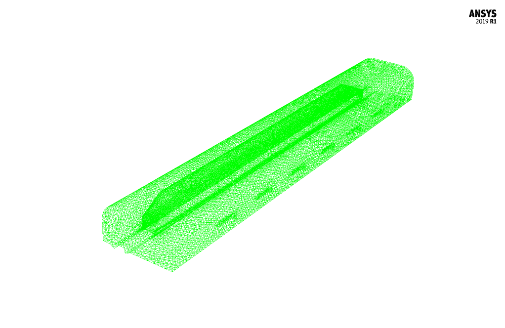
The geometry of the present model is drawn by Design Modeler software. The geometry of this model is related to a subway station that includes a subway line with rails.
Set-up & Solution
| Models | ||
| Viscous | k-epsilon | |
| k-epsilon model | RNG | |
| Near-wall treatment | standard wall function | |
| Species | Species Transport | |
| number of volumetric species | 2 (air & pollutant gas) | |
| Energy | On | |
| Boundary conditions | ||
| Inlet-Doors | Velocity Inlet | |
| velocity magnitude | 0.1 m.s-1 | |
| temperature | 300 K | |
| pollutant mass fraction | 1 | |
| Inlet-Subway | Pressure Inlet | |
| gauge pressure | 0 Pascal | |
| temperature | 300 K | |
| pollutant mass fraction | 0 | |
| Outlet-Panels | Exhaust Fan | |
| gauge pressure | 0 Pascal | |
| pressure jump | 1000000 Pascal | |
| Wall | Wall | |
| wall motion | stationary wall | |
| heat flux | 0 W.m-2 | |
| Methods | ||
| Pressure-Velocity Coupling | SIMPLE | |
| pressure | Second-order | |
| momentum | First-order upwind | |
| turbulent kinetic energy | First-order upwind | |
| turbulent dissipation rate | First-order upwind | |
| pollutant | First-order upwind | |
| energy | First-order upwind | |
| Initialization | ||
| Initialization methods | Standard | |
| velocity magnitude | 0 m.s-1 | |
| temperature | 300 K | |
| pollutant mass fraction | 0 | |
Pollution Ventilation in a Subway Result
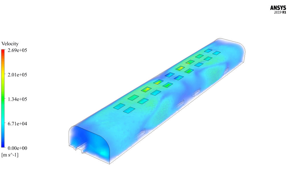
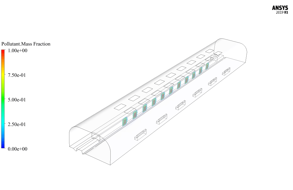
After simulation, 3D contours of pressure, velocity, and mass fraction of pollutants are obtained. The contour of pollutants indicates that the performance of the air-conditioning system of the subway station is optimal.
Pollutants enter the station through subway doors but do not spread into space because the use of powerful fans of the air conditioning system on the roof of the station causes the polluted air to be transferred to the outside environment.


Reviews
There are no reviews yet.