Proton Exchange Membrane Fuel Cell (PEMFC), Paper Numerical Validation, ANSYS Fluent
$450.00 $225.00 Student Discount
- This project numerically simulates the PEM Fuel Cell using ANSYS Fluent software.
- We design the 3-D model with the Design Modeler software.
- We mesh the model with ANSYS Meshing software and the Structured mesh including 270,0000 elements is generated.
- We use the Fuel Cell and Electrolysis Model to define a fuel cell system.
- We used the PEMFC sub-model to define a proton-exchange membrane fuel cell.
- We used the Species model to define H2, O2, and H2O.
- The present CFD work is Validated with a reference Article.
To Order Your Project or benefit from a CFD consultation, contact our experts via email (info@mr-cfd.com), online support tab, or WhatsApp at +44 7443 197273.
There are some Free Products to check our service quality.
If you want the training video in another language instead of English, ask it via info@mr-cfd.com after you buy the product.
Description
Description
In this project, we performed the CFD simulation of a Proton Exchange Membrane Fuel Cell (PEMFC) via ANSYS Fluent software.
This product is based on the simulation of a reference article “Thermal and electrochemical performance analysis of a proton exchange membrane fuel cell under assembly pressure on gas diffusion layer“. Then, the results of the present work are compared and validated with the reference article.
A fuel cell is an energy conversion device that converts chemical energy into electrical energy. In other words, a fuel cell produces electricity through a chemical reaction.
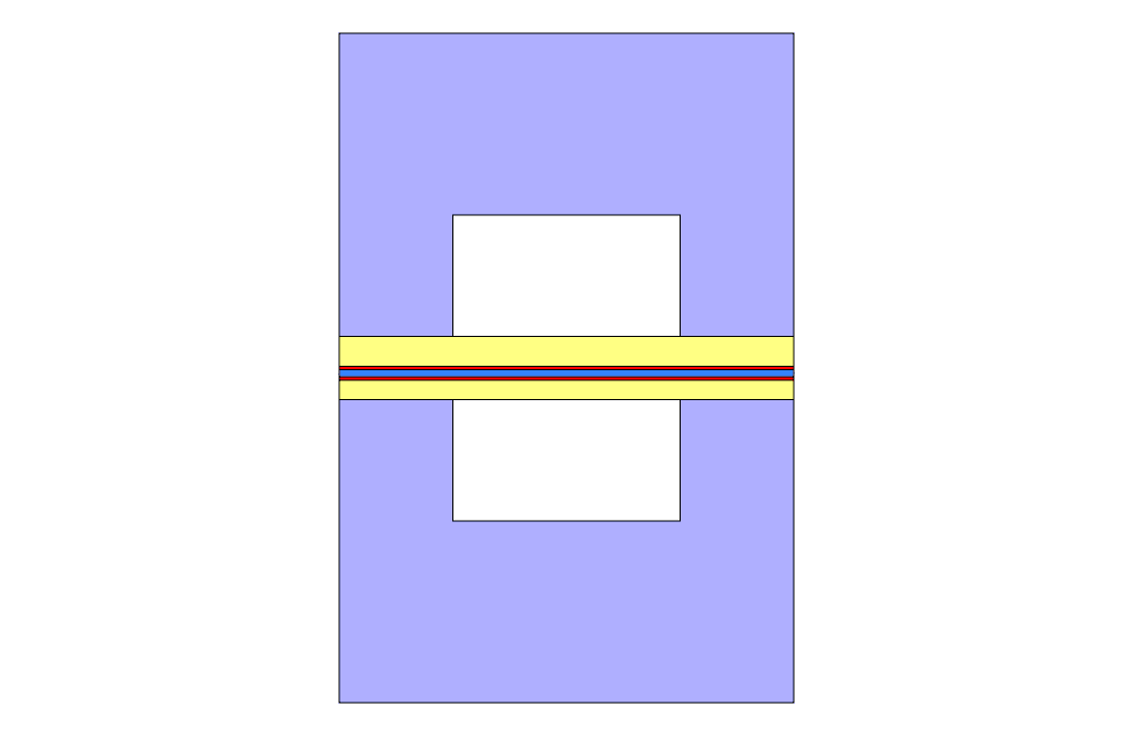
A fuel cell consists of the anode and cathode sides, connected by the electrolyte membrane layer. Each anode or cathode side includes a catalyst layer, a gas diffusion layer, a current collector, and a flow channel.
Hydrogen is fed to the anode side and oxygen is fed to the cathode side. As a result of electrochemical reactions, electricity and water are produced.
Methodology
We performed the simulation process via ANSYS Fluent software. First, we modeled the geometry in 3D using Design Modeler software. Next, we meshed the model using ANYS Meshing software. The meshing is Structured, and 270,000 cells are generated.
In the simulation procedure, we used the Fuel Cell and Electrolysis model to define the fuel cell system. Then, we used the PEMFC sub-model to define the proton-exchange membrane fuel cell.
When we use the fuel cell model, the Species Transport model is automatically enabled. The species transport model defines the species participating in the fuel cell process, including H2, O2, and H2O.
Conclusion
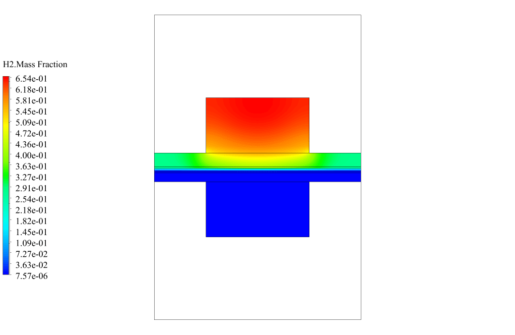
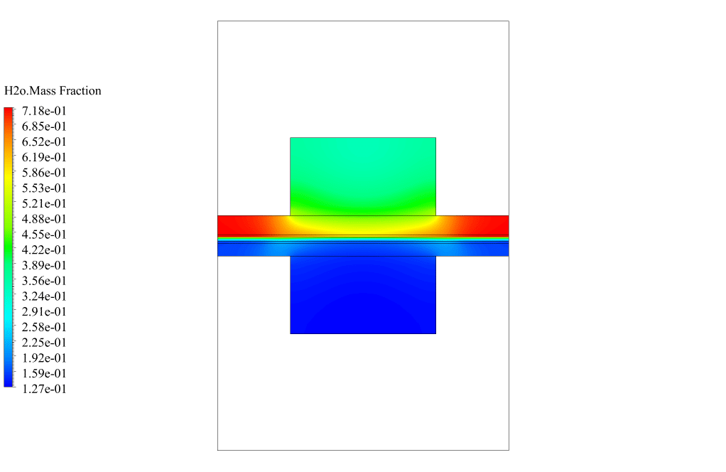
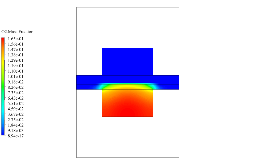
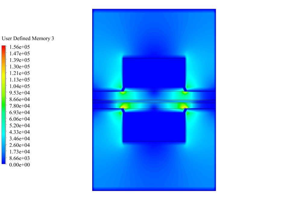
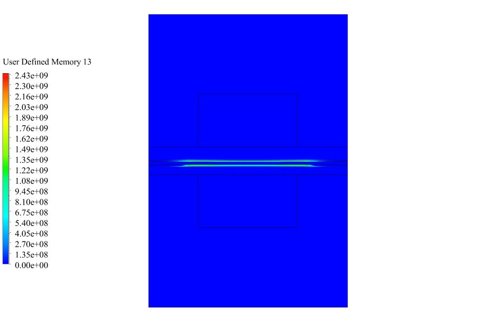
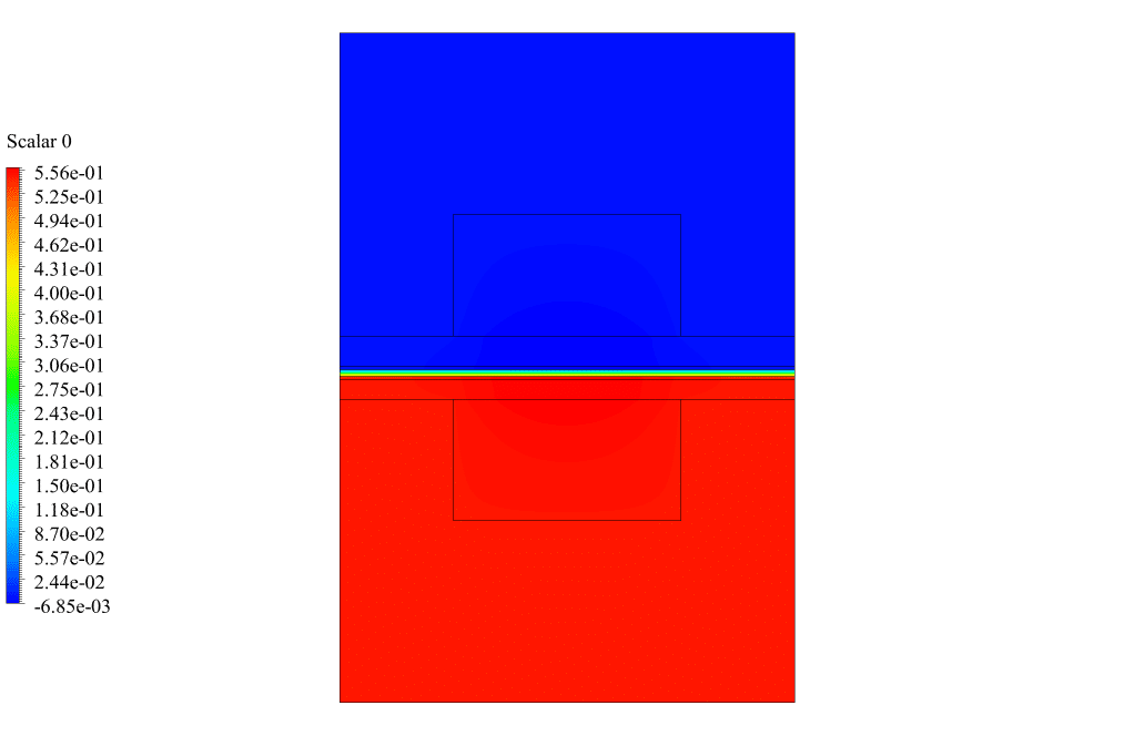
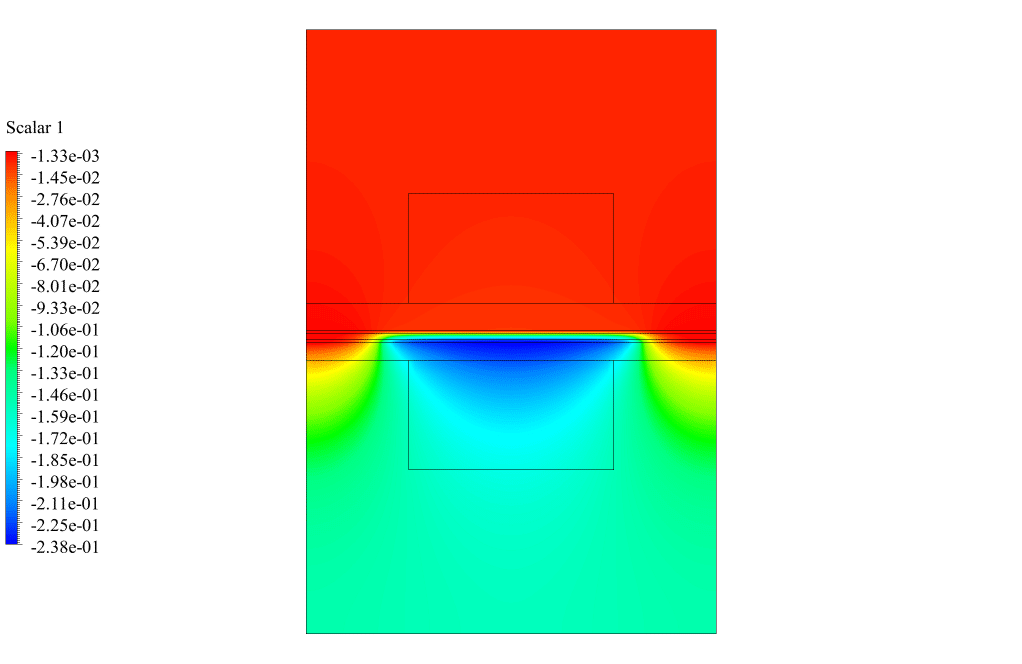
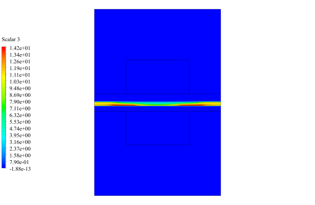
In the post-processing, we obtained the contours according to electric potential (UDS0), protonic potential (UDS1), water content (UDS3), current flux density magnitude (UDM3), transfer current (UDM13), and mass fraction of H2, O2, and H2O.
The H2, O2, and H2O mass fraction contours show that hydrogen flows through the anode side, oxygen flows through the cathode side, and water is produced on the anode side. This behavior confirms that the present fuel cell system operates correctly.
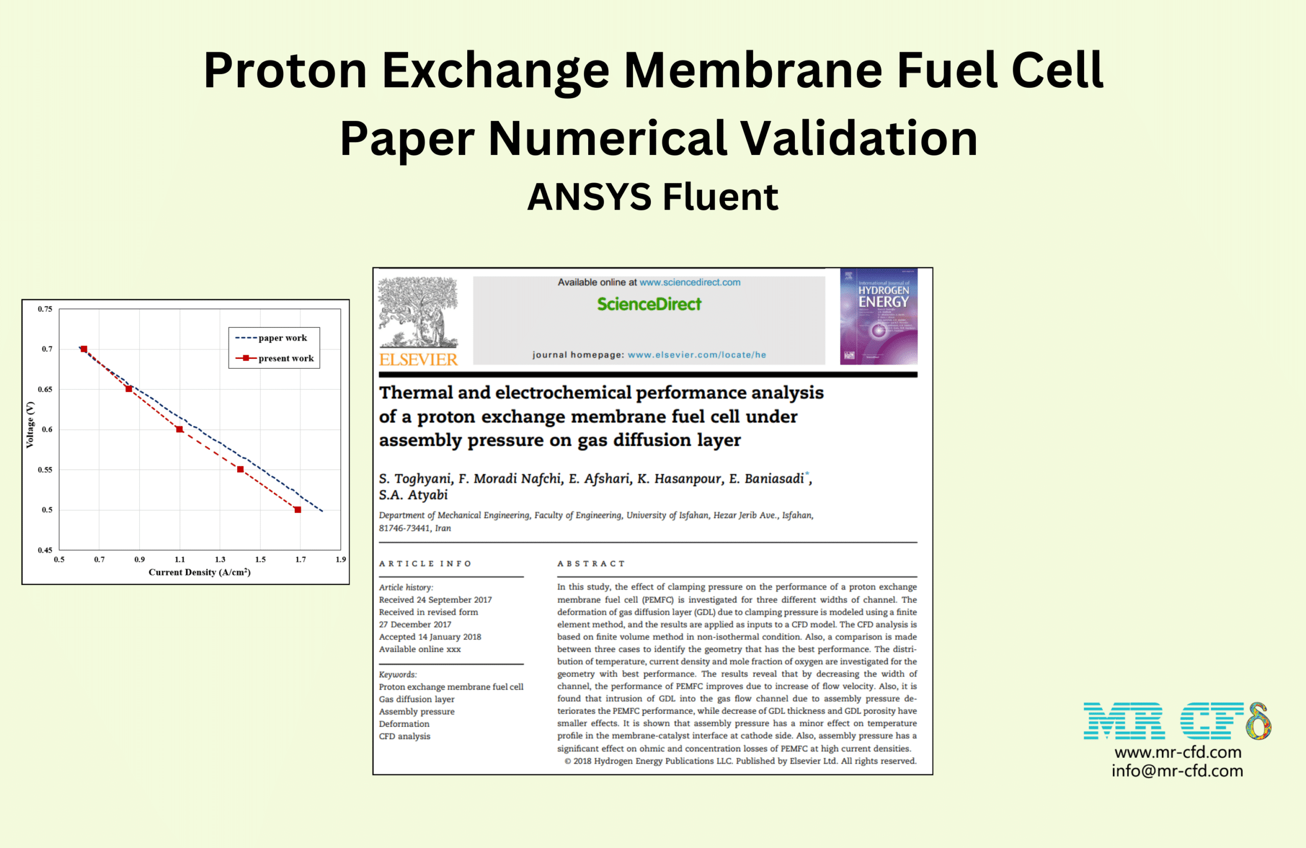
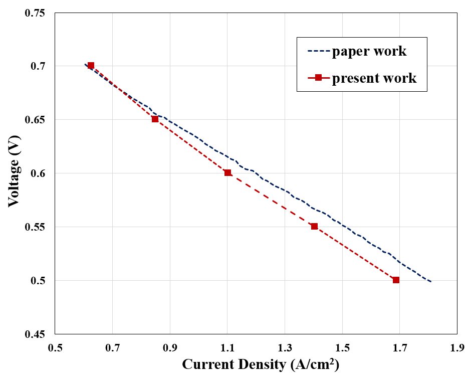
The validation of the present numerical study is based on one of the Polarization plots mentioned in the reference article. The polarization curve presents the Current Density based on the Voltage in the fuel cell system.
Therefore, we implemented the present simulation project in several cases. In each study case, we defined different voltages (0.5 to 0.7 volts) and computed the current density for each case.
We presented the results in the following plot and table, showing that the present numerical work is highly accurate.


Reviews
There are no reviews yet.