Proton Exchange Membrane Fuel Cell, PEMFC, Stack Fuel Cell System
$240.00 $120.00 Student Discount
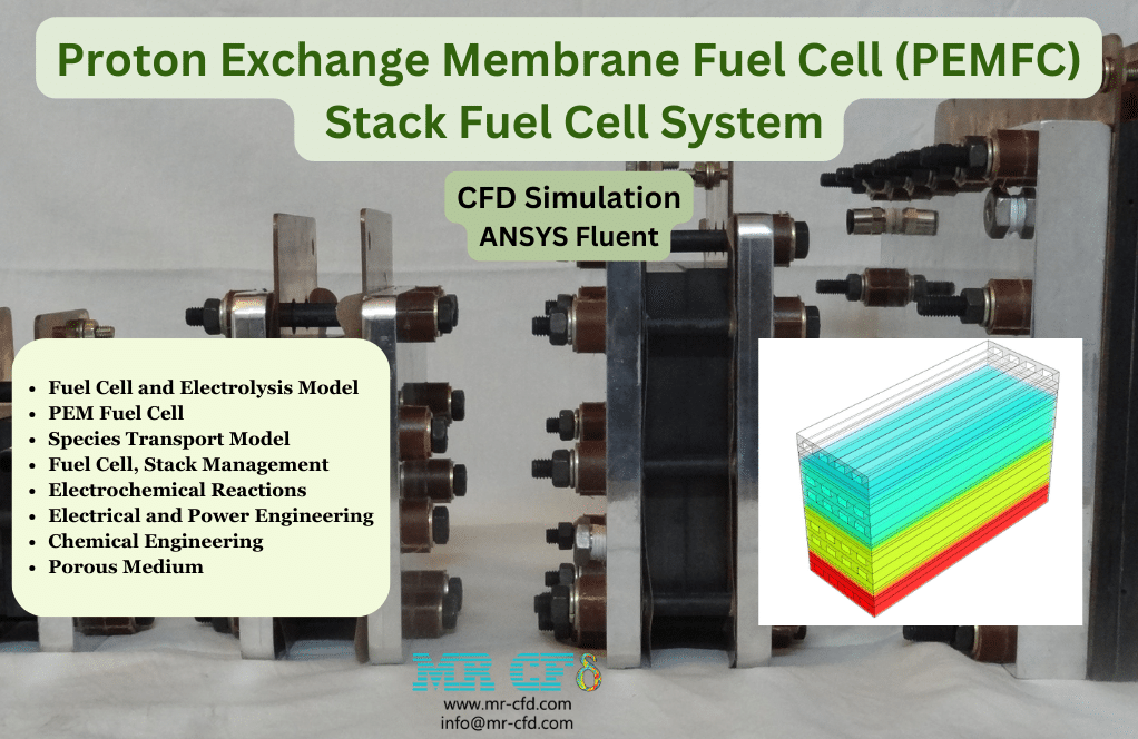
- In this project, we perform the numerical simulation of a PEM Fuel Cell Stack System using ANSYS Fluent software.
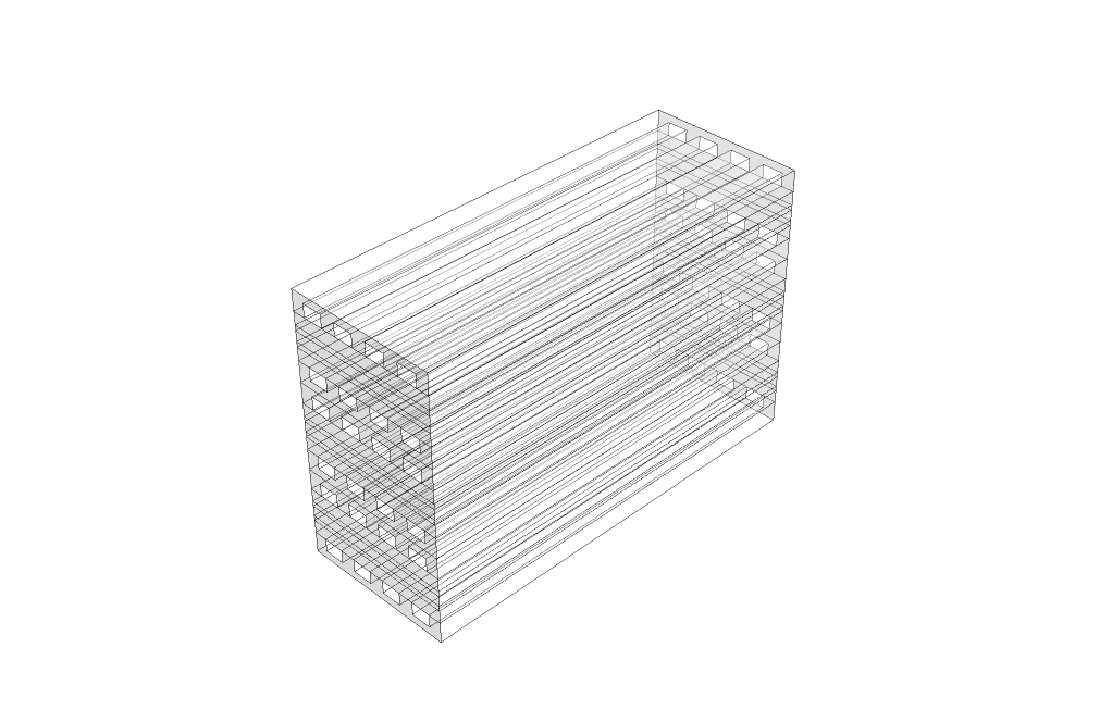
- We designed the geometry of the model in 3D using Design Modeler software.
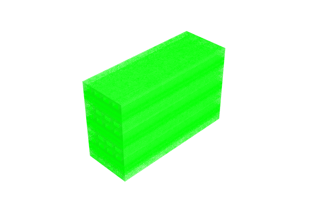
- We meshed the model using ANSYS Meshing software, and 9,946,409 cells have been generated.
- We used the Fuel Cell and Electrolysis model and the PEMFC submodel to define the proton-exchange membrane fuel cell.
- We applied the Stack Management option to define multiple fuel cell units.
- The Species Transport model is automatically activated because of using the fuel cell model.
To Order Your Project or benefit from a CFD consultation, contact our experts via email (info@mr-cfd.com), online support tab, or WhatsApp at +44 7443 197273.
There are some Free Products to check our service quality.
If you want the training video in another language instead of English, ask it via info@mr-cfd.com after you buy the product.
Description
Proton Exchange Membrane Fuel Cell, PEMFC, Stack Fuel Cell System, CFD Simulation, ANSYS Fluent Tutorial
Description
In this project, we perform the numerical simulation of a Fuel Cell Stack using ANSYS Fluent software.
This product is the 4th chapter of the Fuel Cell Training Course.
A fuel cell is an energy conversion device that converts the chemical energy of fuel into electrical energy. A fuel cell produces electricity through a chemical reaction.
Fuel cells have two electrodes called an anode and a cathode. These chemical reactions occur in these electrodes and lead to electricity production.
In addition, fuel cells have an electrolyte and a catalyst. The electrolyte layer transports charged particles (ions) between the electrodes, while the catalyst layer increases the speed of reactions in the electrode layers.
The hydrogen is fed to the fuel cell as the main fuel. However, oxygen is also required for the reaction to take place.
One of the most important advantages of the fuel cell is that electricity is produced with the least amount of pollution. Most of the oxygen and hydrogen input to the fuel cell is eventually released as a harmless product, that is, water.
There are different types of fuel cells. In this project, we have simulated the proton exchange membrane fuel cell (PEMFC).
Practically, each fuel cell produces a very low amount of current. So, We used a large number of cells in large groups called a stack to generate electricity. In a fuel cell stack, several individual fuel cell units are combined.
Methodology
We simulated this project based on the CFD method by ANSYS Fluent software.
First, we designed the geometry of the model in 3D using Design Modeler software. The computational domain of the model is related to the interior space of a fuel cell.
Then, we meshed the model using ANYS Meshing software. The meshing is unstructured, and 9046409 cells are generated.
Finally, we performed the simulation process in Fluent software.
For this simulation, we used the fuel cell model in Ansys Fluent software. The fuel cell model is an add-on module in Ansys Fluent software.
There are three different fuel cell add-on modules available in the software. We have used the fuel cell and electrolysis model. Here, there are three submodels. We have used the PEMFC model.
In the fuel cell model setting, we determine the different layers of the fuel cell. These layers include the cathode and anode layers, along with the electrolyte layer. Each of the anode and cathode layers consists of current collectors, gas diffusion layers (electrode layers), catalyst layers, and flow channels.
Since we combined several fuel cell units for this fuel cell system, we need to use the stack management option.
Since we used the fuel cell model, the species transport model is automatically activated. The species transport model defines the species present in the fuel cell, including H2, O2, and H2O.
Conclusion
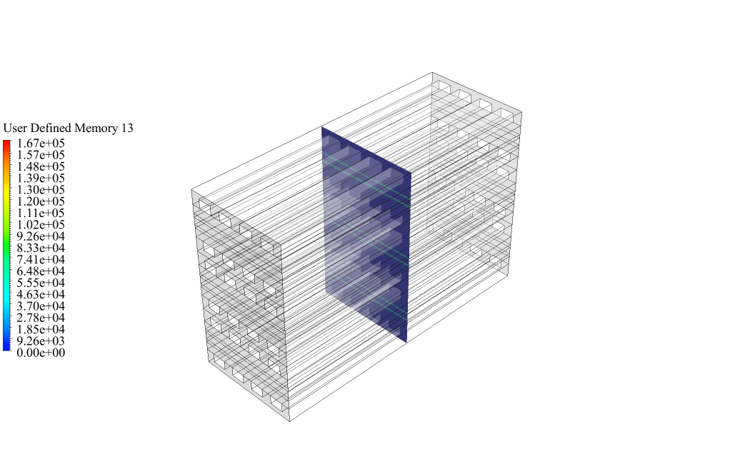
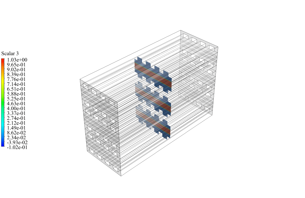
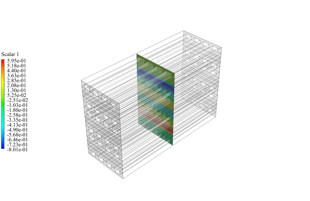
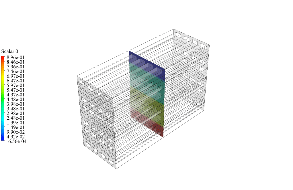
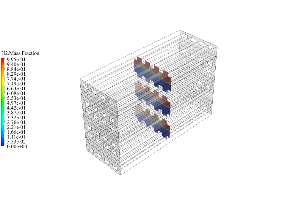
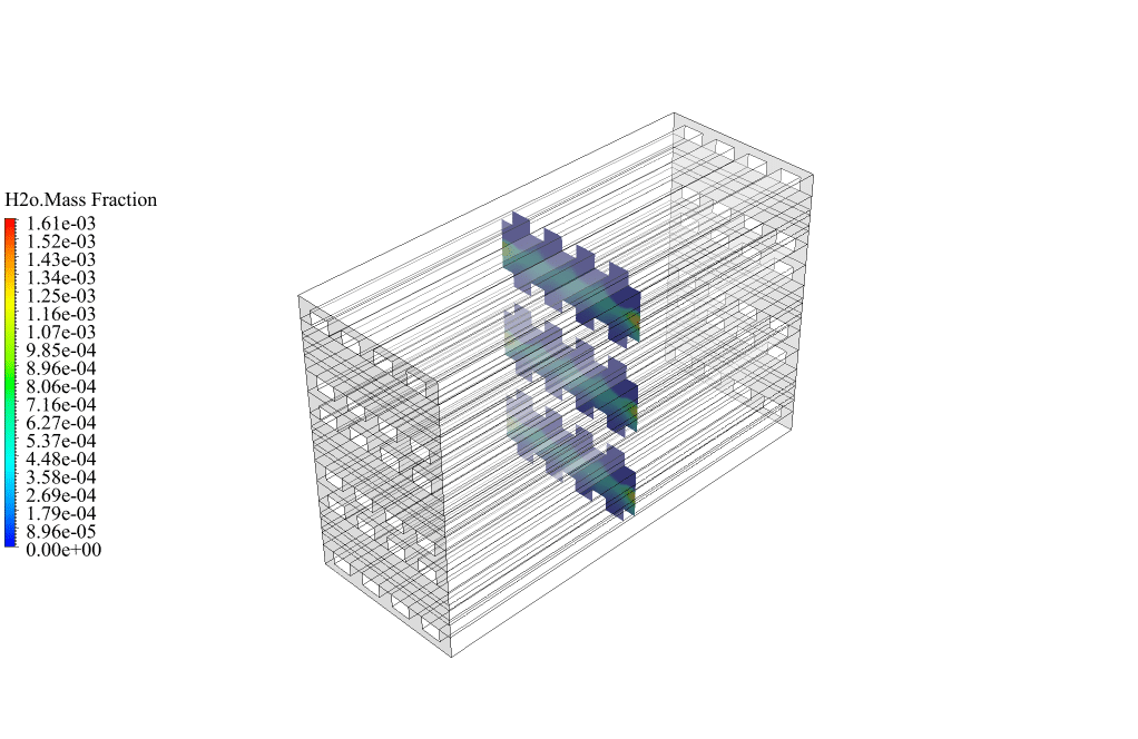
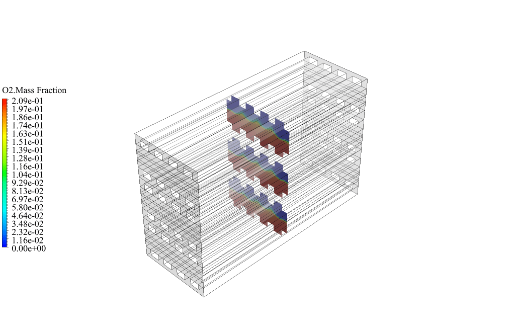
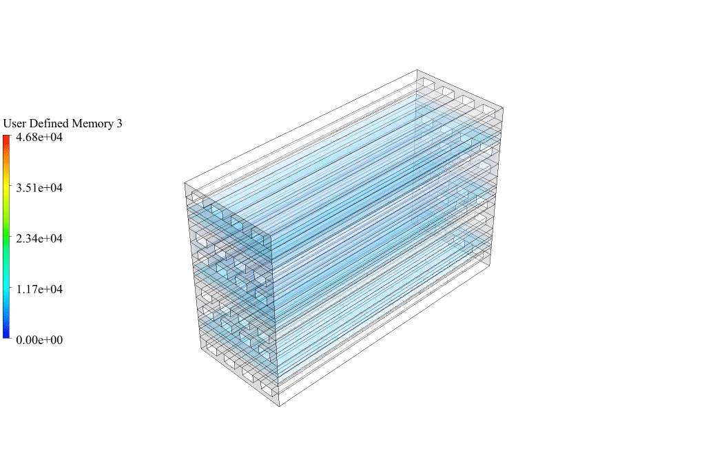
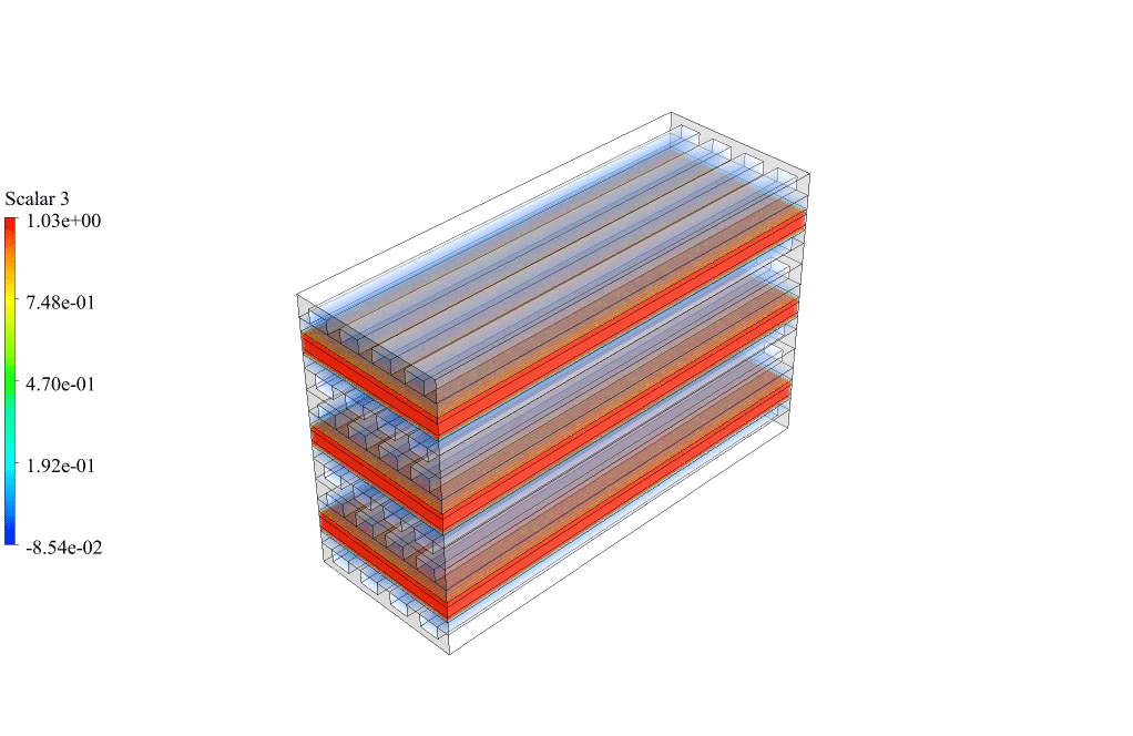
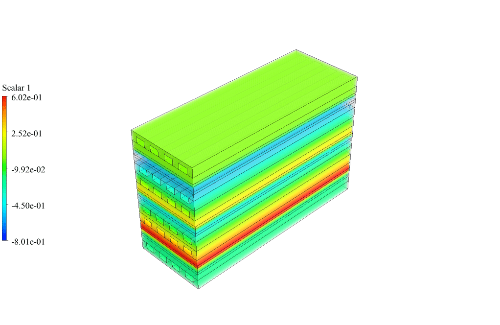
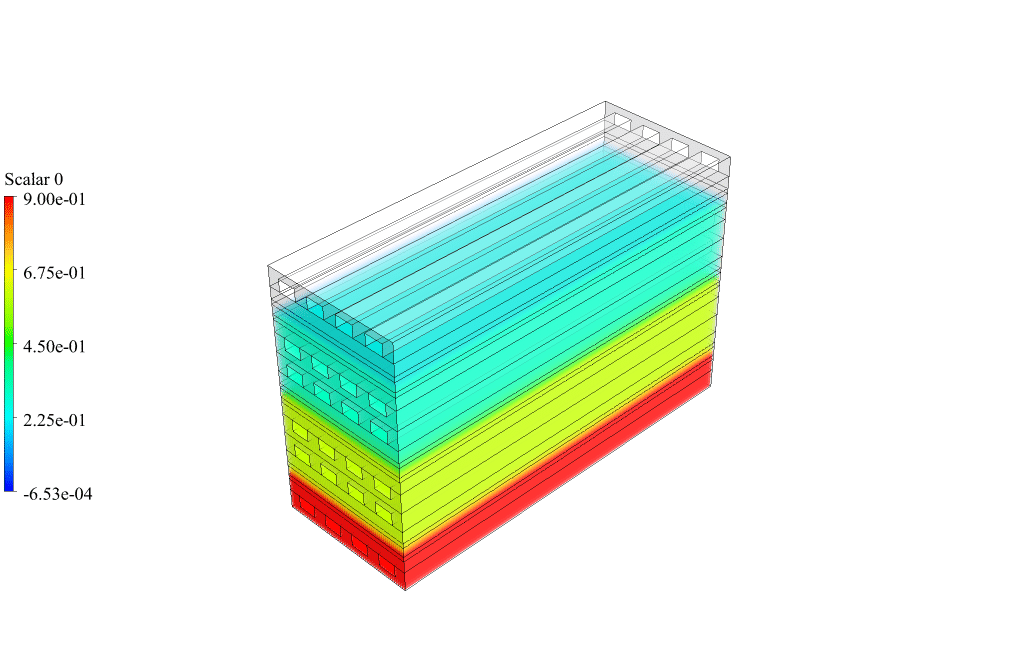
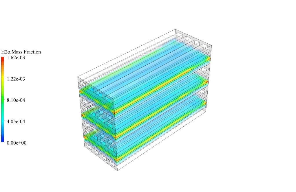
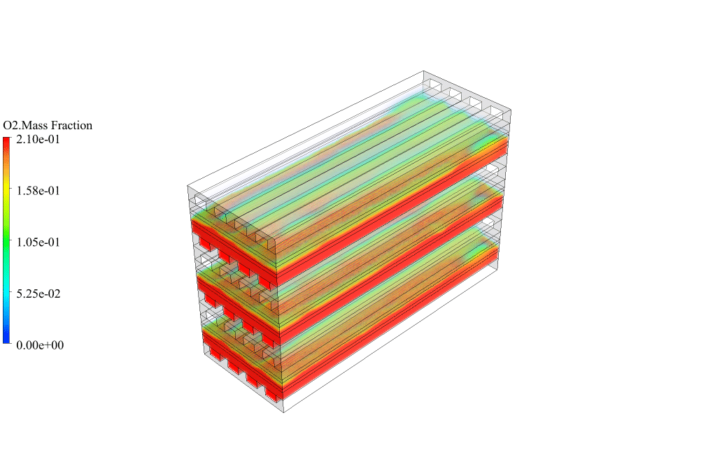
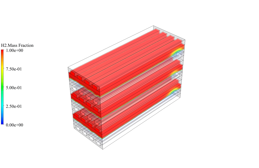
After conclusion, we have obtained the contours related to electric potential, protonic potential, water content, current flux density magnitude, transfer current, and mass fraction of H2, O2, and H2O.
The H2, O2, and H2O mass fraction contours show that hydrogen enters from the anode sides, oxygen enters from the cathode sides, and water is produced in the cathode sections. This behavior is exactly according to the functional mechanism of the PEMFC fuel cell system.
When we use the fuel cell model, some user-defined scalars (UDS) are enabled. Here, we obtained the contours of electric potential (scalar 0), protonic potential (scalar 1), and water content (scalar 3). These contours show that the potential equations of the fuel cell model are solved correctly. Hence, the effect of electrons and protons in fuel cell layers is understandable. In addition, the production of water in the fuel cell is also significant.
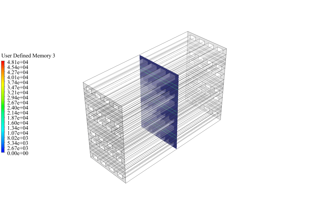
Also, when we use the fuel cell model, several user-defined memories (UDM) are enabled. Here, we obtained contours of current flux density magnitude (user-defined memory 3) and transfer current (user-defined memory 13). These contours show that the current is generated based on the voltage we defined for the fuel cell.



Rupert Haag –
Harnessing truly clean energy using the Chemical energy in fuel amazes me every time I read about it. And to see it all demonstrated via a computer model feels like catching a glimpse of the future. I’m thrilled with the simulation results and clarity it provides, kudos for making such an intricate process so accessible!
MR CFD Support –
Thank you for your wonderful feedback! We’re thrilled to hear that our Proton Exchange Membrane Fuel Cell simulation met your expectations and provided clear insight into the technology’s workings. Our goal is to make complex concepts easily understandable and accessible. We appreciate your support and are pleased our efforts resonated with you.
Janiya Lowe –
I was amazed by the level of detail in this product! The explanation of the cooling system utilizing the cooling channels is intriguing. Can you tell me more about how the performance of the cooling system was validated through the simulation?
MR CFD Support –
In the simulation, the performance of the cooling system is assessed by looking at the temperature contours. These contours demonstrate the efficacy of the cooling channels in maintaining the fuel cell temperature within optimal limits despite the high operational temperatures of the PEMFC. If the cooling system works properly, the temperature distribution should be relatively uniform and within acceptable ranges, ensuring that overheating does not occur. The validation is done by comparing the simulated temperatures with expected temperature values or design targets.
Margie West –
This product seems comprehensive; I was just wondering though, is there a part of the tutorial that explains how to analyze the impact of different operating conditions on fuel cell performance?
MR CFD Support –
Absolutely, the tutorial includes guidance on assessing the impact of varying operating conditions, such as temperature and pressure, and how these changes influence the overall performance and efficiency of the fuel cell. Various scenarios can be simulated to understand the behavior of the system under different conditions.
Dr. Maybelle Wilderman –
I’m impressed with the level of detail provided for the PEMFC stack simulation! Can you expand on how the cooling system efficiency impacts the overall performance of the PEMFC?
MR CFD Support –
The efficiency of the cooling system has a significant impact on the performance of the PEMFC. An effective cooling system ensures that the fuel cell operates within an optimal temperature range, which is crucial for maintaining the integrity of the components and maximizing the electrochemical reaction efficiency. If the cooling system functions properly, it prevents overheating, which can lead to catalyst degradation, membrane drying, or thermal stresses. Therefore, proper cooling contributes to both the longevity and the electrical efficiency of the PEMFC stack.
Dr. Jaclyn Rutherford –
The simulation results for the PEMFC are impressive – particularly how they show the temperature controls and reaction behaviors inside the system. It’s clear the cooling system is effective. Kudos to the MR CFD team for this detailed tutorial!
MR CFD Support –
Thank you very much for your positive feedback! We’re delighted to hear that our Proton Exchange Membrane Fuel Cell tutorial was informative and showcased the effectiveness of the cooling channels. We truly appreciate you taking the time to compliment our learning products. Your encouragement supports our commitment to continuously provide high-quality educational content. If there is anything else you are curious about or any more topics you’d like us to cover, please don’t hesitate to let us know. Thank you for choosing MR CFD!
Marilie Weimann –
The tutorial mentions ‘cooling channels’ to manage the high operating temperatures. Could you elaborate on how these cooling channels are implemented in the simulation model and their effectiveness in temperature control?
MR CFD Support –
In the simulation model for the PEMFC Stack Fuel Cell, cooling channels are incorporated on both sides of the anode and cathode electrodes to manage high operating temperatures. Their geometry is designed using the Design Modeler software and integrated within the computational domain to mimic the physical flow of coolant. The effectiveness of these cooling channels is demonstrated by the temperature contours obtained from the CFD analysis. They clearly show a reduction in fuel cell temperature where the cooling channels are present, indicating their vital role in maintaining operational temperatures and thus ensuring proper functioning of the fuel cell system.
Norene Orn –
I’ve read about the temperature contours showing high fuel cell temperatures. Can you clarify how the cooling channels are integrated with the rest of the fuel cell system within the simulation?
MR CFD Support –
In this simulation, the cooling channels are designed to lie perpendicular to the direction of the reactant flow, parallel and adjacent to both the anode and cathode layers. They circulate a coolant fluid which absorbs heat from the cell and transfer the heat away, maintaining the operation of the fuel cell within the desired temperature range.
Dr. Catalina Leuschke II –
The description of this product was exceptionally informative! I appreciate the detail provided on the methodology and the results, which leave little room for questions. It’s also great to hear that the simulation manages to solve the potential equations correctly and that the cooling system is effective. Well done to MR CFD for a robust and insightful learning product.
MR CFD Support –
Thank you for your kind words and enthusiasm regarding the PEMFC Stack Fuel Cell System CFD simulation tutorial. We’re delighted that our product met your needs effectively and provided you with the detailed insights you were looking for. Customer satisfaction is our top priority, and we’re thrilled that we could enhance your understanding of such a complex topic. If you ever have more inquiries or need further assistance in the future, please do not hesitate to reach out to us. Thank you once again for choosing MR CFD!
Nikolas Streich PhD –
I absolutely loved the depth of analysis provided in the PEMFC Stack Fuel Cell System tutorial. The comprehensive steps in modeling and simulation using ANSYS Fluent paved the way for a clear understanding of fuel cell operations, especially the cooling system’s effectiveness. The simulation effectively showcased the temperature control and the chemical processes involved.
MR CFD Support –
Thank you so much for your kind words! We’re thrilled to hear you found the PEMFC Stack Fuel Cell System tutorial to be comprehensive and informative. It’s our goal to ensure our tutorials are detailed and helpful for understanding complex systems like fuel cells. We appreciate your feedback and are glad the tutorial enhanced your understanding of the operation and simulation of fuel cell systems in ANSYS Fluent. If there’s ever more we can do to assist in your learning journey or simulations, don’t hesitate to reach out!
Larue Ferry –
Wow! The level of detail and the CFD analysis for the PEMFC stack fuel cell system sound impressive. The use of cooling channels to manage high operational temperatures showcases an important engineering solution. Well done!
MR CFD Support –
Thank you for your kind words! We’re thrilled to hear that you appreciate the intricacies and depth of the computational fluid dynamics (CFD) analysis done on the PEMFC stack. Our aim is always to provide comprehensive insights and solutions in our CFD simulations. Your feedback motivates us to continue delivering high-quality simulations and analyses.