Water-Cooled Photovoltaic Thermal (PVT) System using nanofluid, Paper Numerical Validation
$300.00 $150.00 Student Discount
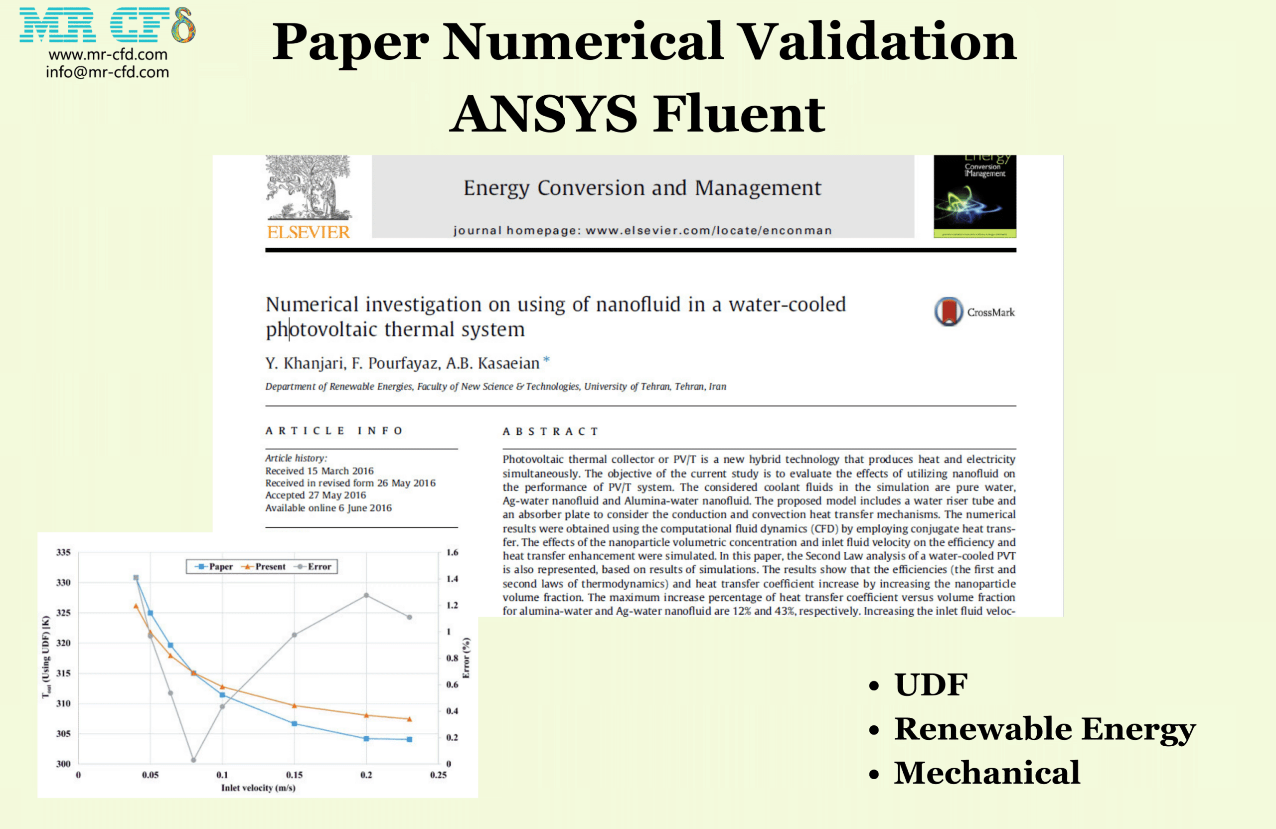
- The current CFD Analysis numerically Validates the Paper “Numerical investigation on using of nanofluid in a water-cooled photovoltaic thermal systems” via ANSYS Fluent software.
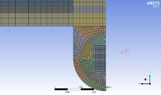
- We have designed and meshed the geometry using Design Modeler, producing structured cells.
- UDF in SOURCE Macro is used for the heat generation.
To Order Your Project or benefit from a CFD consultation, contact our experts via email (info@mr-cfd.com), online support tab, or WhatsApp at +44 7443 197273.
There are some Free Products to check our service quality.
If you want the training video in another language instead of English, ask it via info@mr-cfd.com after you buy the product.
Description
Water-Cooled Photovoltaic Thermal (PVT) System using nanofluid, Paper Numerical validation
Description
This product is a PVT system simulation in ANSYS Fluent that validates the paper: “ Numerical investigation on using of nanofluid in a water-cooled photovoltaic thermal system“.
The PVT systems are multi-layered, integrated energy solution designed to harness solar energy for both electricity generation and thermal applications:
Power Generation: Light from the sun enters the photovoltaic cells in the middle layer after passing through the glass layer. A portion of the solar energy is converted by these cells into electrical energy; the efficiency of this conversion varies depending on the cell technology and the surrounding conditions.
Thermal Energy Collection: The copper layer under the photovoltaic cells subsequently absorbs the heat produced by the unconverted solar energy. This heat is converted into a circulating fluid that can be utilized for thermal applications such as water heating or space heating.
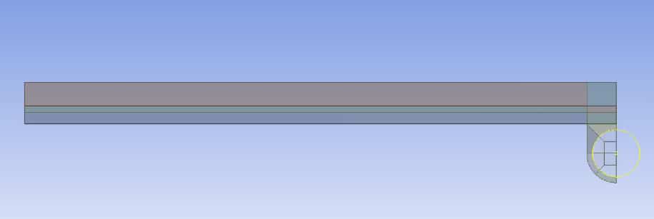
The model consists of three parts:
1. Glass Layer (Upper Layer) made of high-transmissivity glass that acts as a protective cover and ensures maximum sunlight penetration with minimal reflection losses.
2. Photovoltaic (PV) Layer (Middle Layer) that is the heart of the electrical energy generation process. It absorbs sunlight and converts it into direct current (DC) electricity through the photovoltaic effect.
3. Copper Absorption Layer (Bottom Layer), known for its excellent thermal conductivity. This part absorbs residual thermal energy from the PV layer and transfers it to a heat transfer fluid, which can be utilized for various heating applications.
The geometry of this project is drawn in Design Modeler and meshed in ANSYS Meshing.
Methodology
This simulation is done steadily and based on the paper we have used the heat source presented in the equation below for the PV layer in the simulations. In this validation, in one case, UDF is written for volumetric heat SOURCE due to its dependence on cell temperature.
And for another case heat source is defined as constant value.
Meanwhile, η_el, or the electrical efficiency of the solar module, depends on the temperature of the PV layer, and is obtained from the following equation.
Conclusion
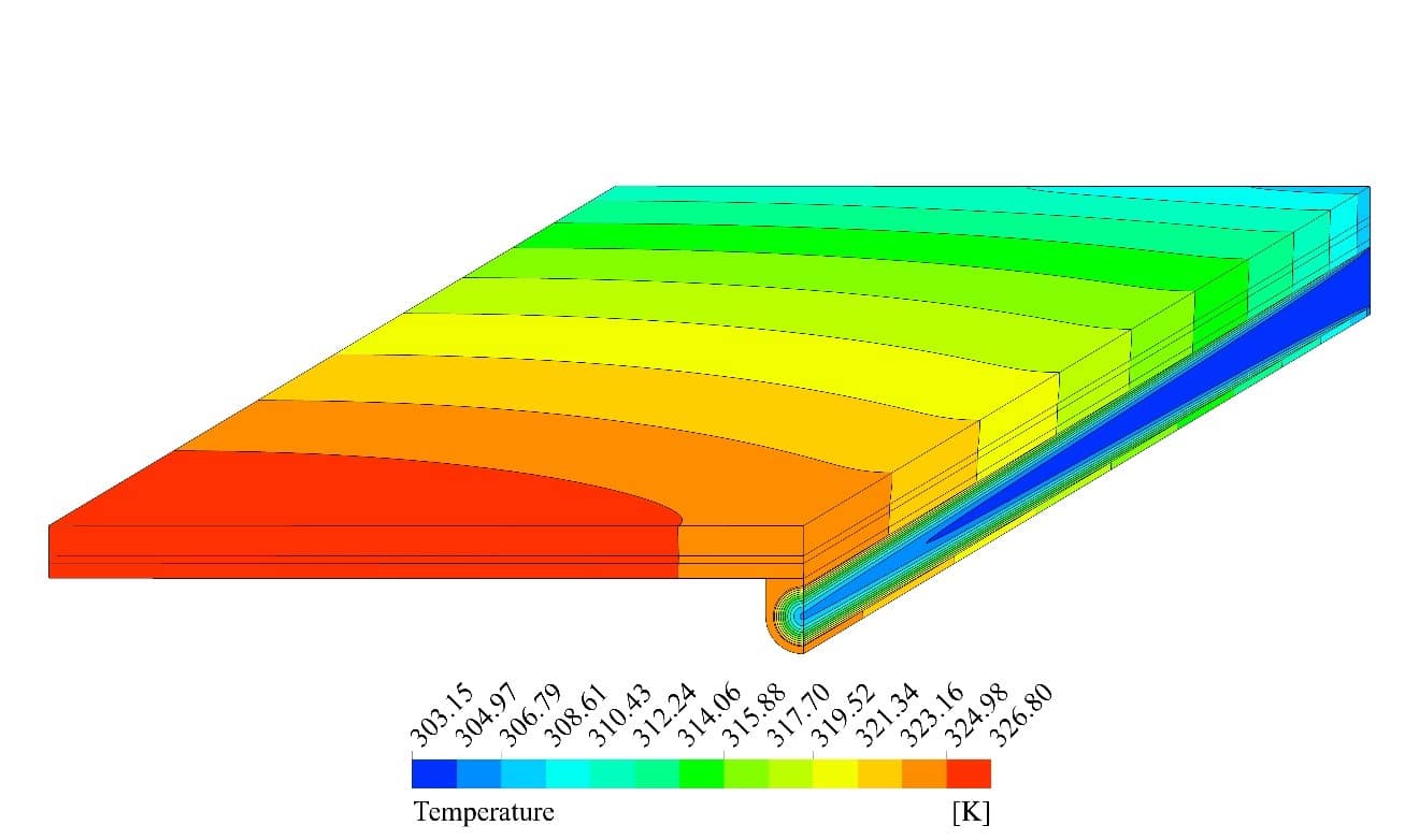
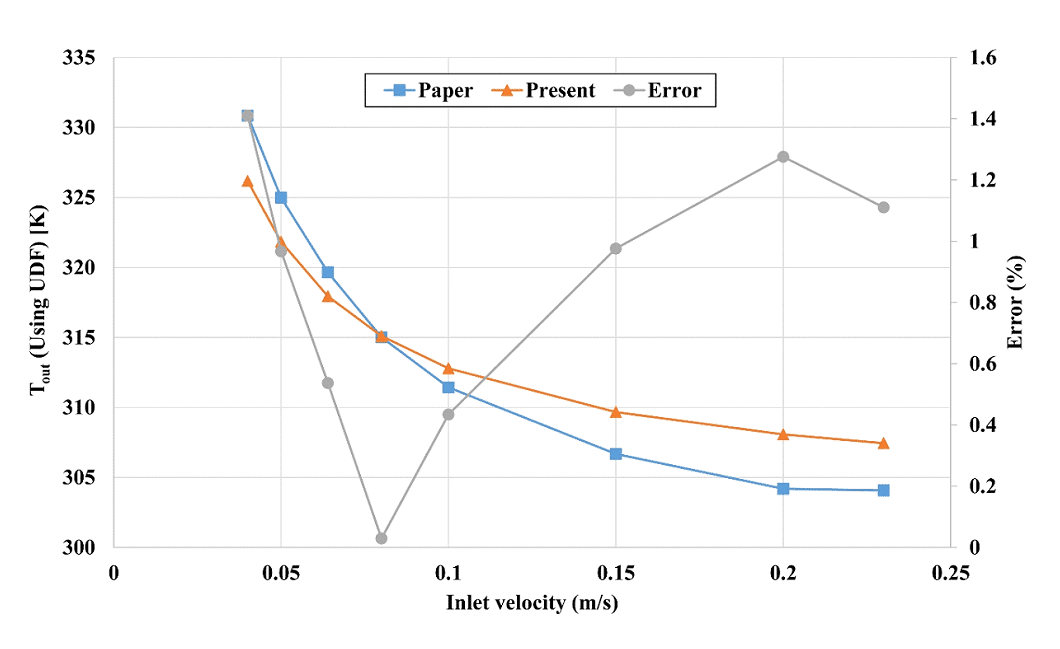
A comparison of the outlet temperature of the heat transfer fluid, which is also used to obtain the thermal efficiency of the system, is presented here. As seen in the following figure , the results in using both heat sources are close to the results presented in the article. In using UDF, the maximum error is about 1.4%, and this error value is nearly 1.3% when using the constant value of volumetric heat. The average error in all speeds using UDF is 0.84%. While using the fixed value of the heat source, this average error is 0.74%.






Reviews
There are no reviews yet.