Quadcopter Fluid-Structure Interaction (FSI) Simulation using ANSYS Fluent
$210.00 $105.00 Student Discount
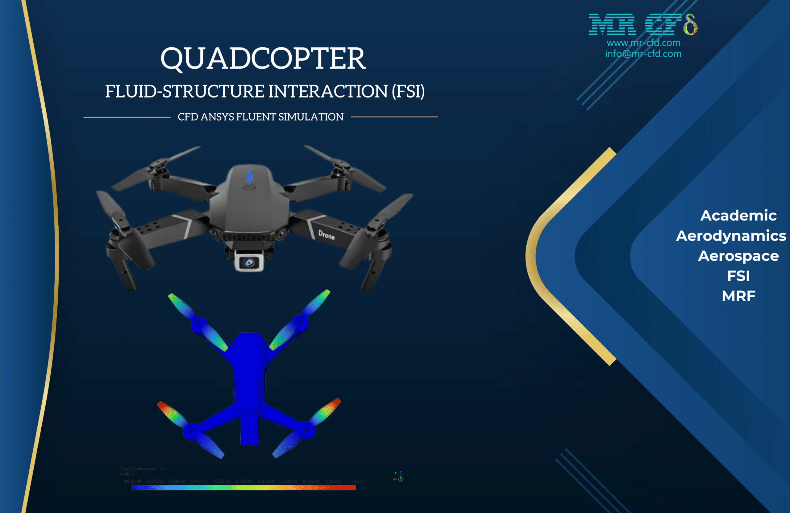
- This study presents a Fluid-Structure Interaction (FSI) simulation of a quadcopter using ANSYS Fluent
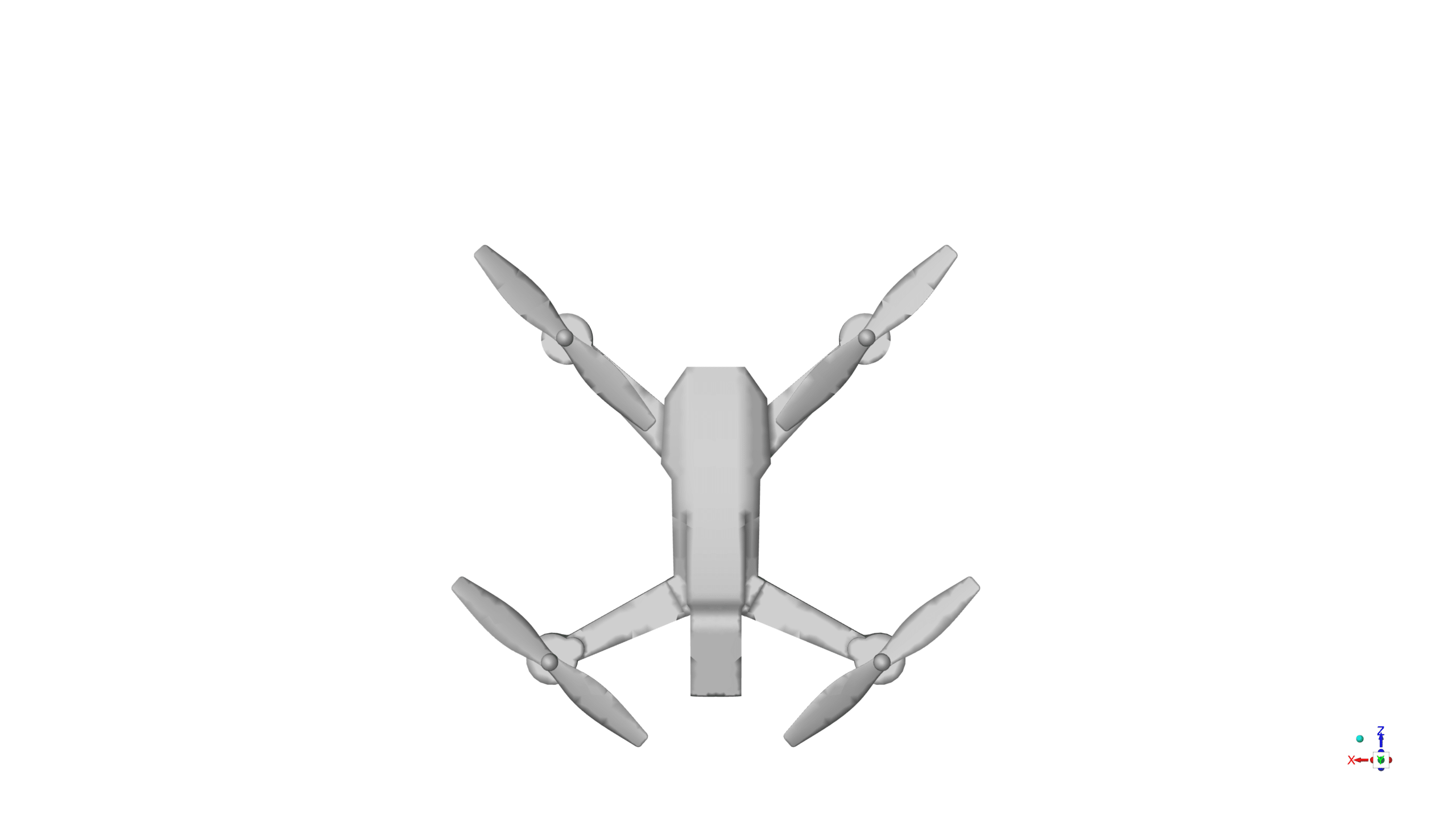
- The quadcopter geometry was created using ANSYS SpaceClaim
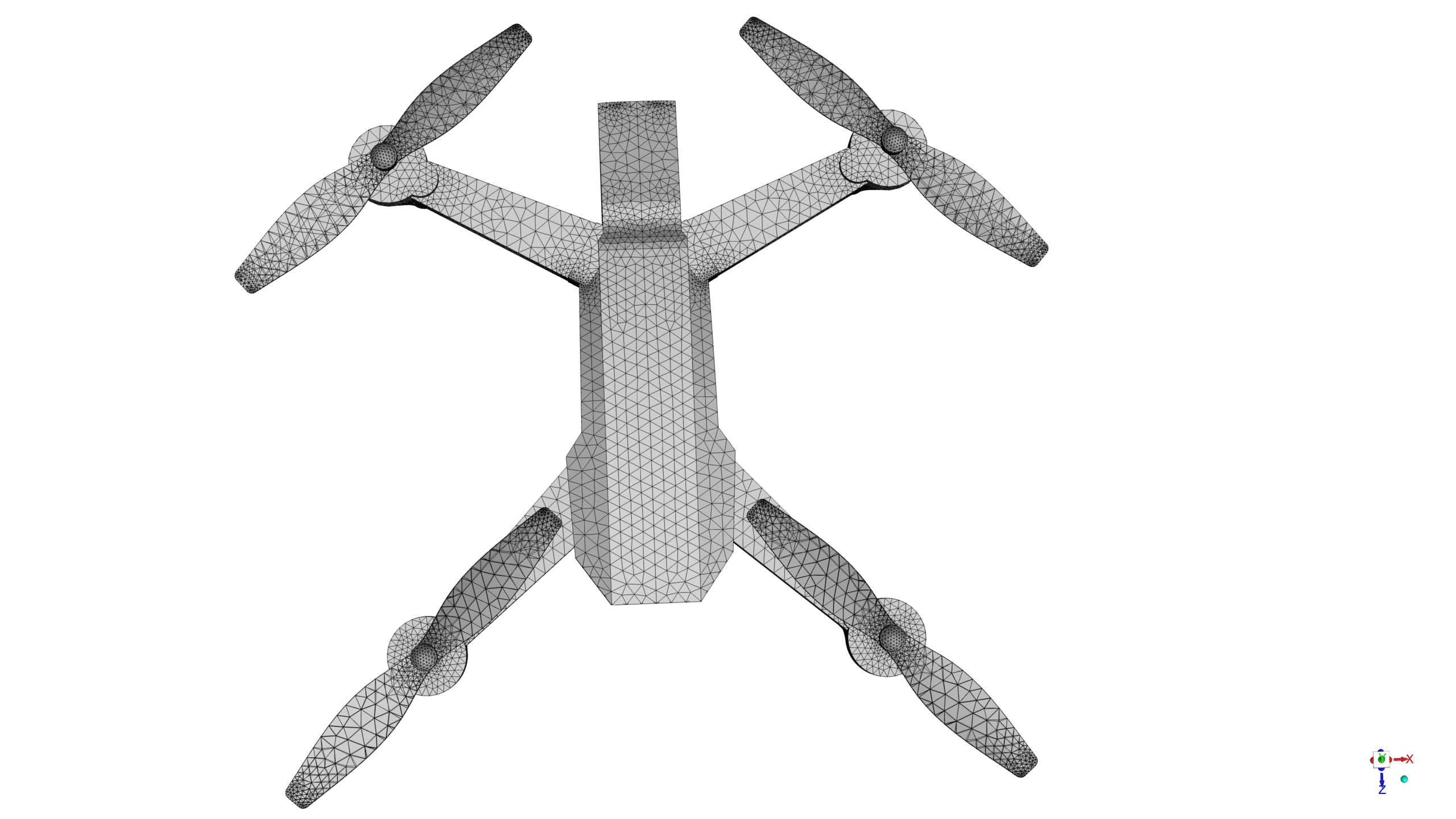
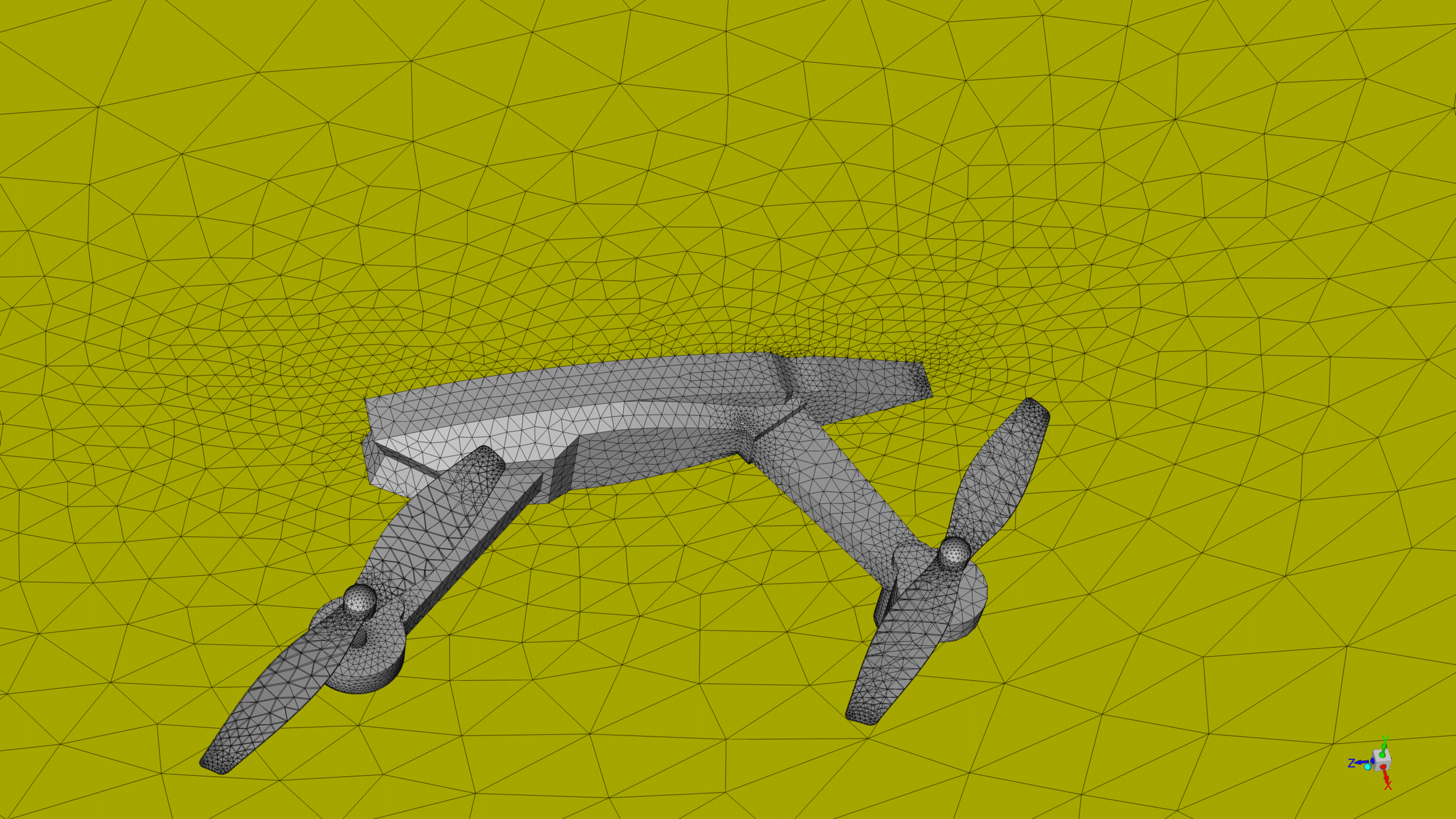
- The model was then meshed using ANSYS Meshing, which generated an unstructured mesh consisting of approximately 499,152 elements
- To accurately capture the blades’ rotation, two frame motion(MRF) zones are applied to the blades.
- The Structure model with the Linear Elasticity option was enabled to investigate the displacement of the blade
To Order Your Project or benefit from a CFD consultation, contact our experts via email (info@mr-cfd.com), online support tab, or WhatsApp at +44 7443 197273.
There are some Free Products to check our service quality.
If you want the training video in another language instead of English, ask it via info@mr-cfd.com after you buy the product.
Description
Description
This study presents a Fluid-Structure Interaction (FSI) simulation of a quadcopter using ANSYS Fluent. The simulation aims to capture the complex interactions between the fluid dynamics and the structural deformations of the quadcopter components.
The FSI simulation couples the fluid flow analysis with the structural deformations of the quadcopter components. ANSYS Fluent, a powerful computational fluid dynamics (CFD) software, is used to solve the governing equations of fluid motion, while the structural solver calculates the deformations and stresses in the structure.
The quadcopter geometry was created using ANSYS SpaceClaim, a powerful 3D modeling software that allows for efficient and flexible design. By leveraging the symmetry design, we can reduce the computational cost of the simulation while maintaining accuracy.
The model was then meshed using ANSYS Meshing, which generated an unstructured mesh consisting of approximately 499,152 elements. The high mesh density ensures accurate resolution of the fluid flow and structural deformations.
Also, you can see the acoustic analysis and Dynamic Stability Derivatives of this product.
Methodology
A pressure-based, transient solver was employed to capture the time-dependent flow characteristics and structural response of the quadcopter.
The SST k-omega turbulence model was chosen to accurately represent the turbulent nature of the flow around the turbine.
To accurately capture the blades’ rotation, two frame motion(MRF) zones are applied to the blades.
The Structure model with the Linear Elasticity option was enabled to investigate the displacement of the blades, allowing for the analysis of fluid-structure interaction.
The domain inlet is set as a velocity-inlet with a uniform velocity of 5 m/s. The domain outlet is defined as a pressure outlet with a gauge pressure of 0 kPa. The quadcopter is modeled as adiabatic walls with a no-slip condition and an intrinsic FSI setup.
The frame motion is set up using the Multiple Reference Frame (MRF) approach with a rotational speed of 600 rpm.
Results
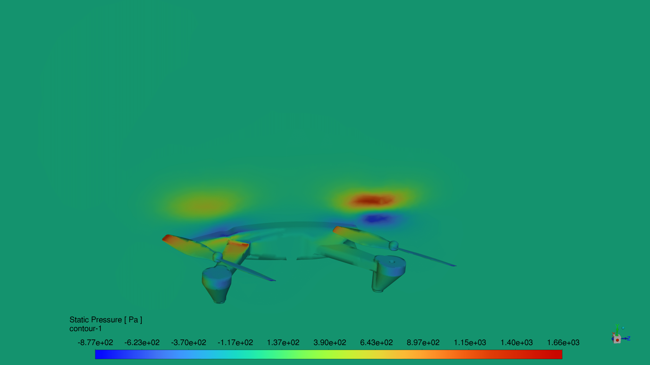
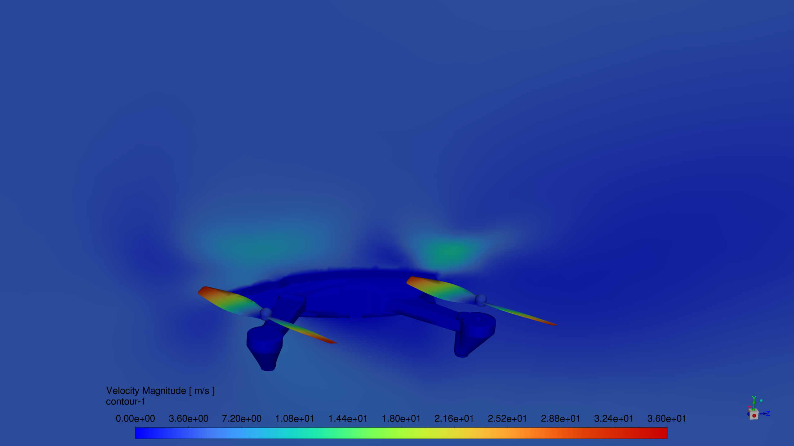
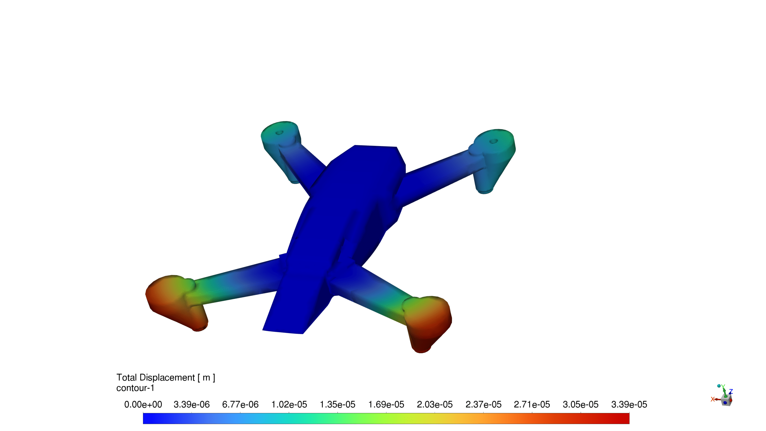
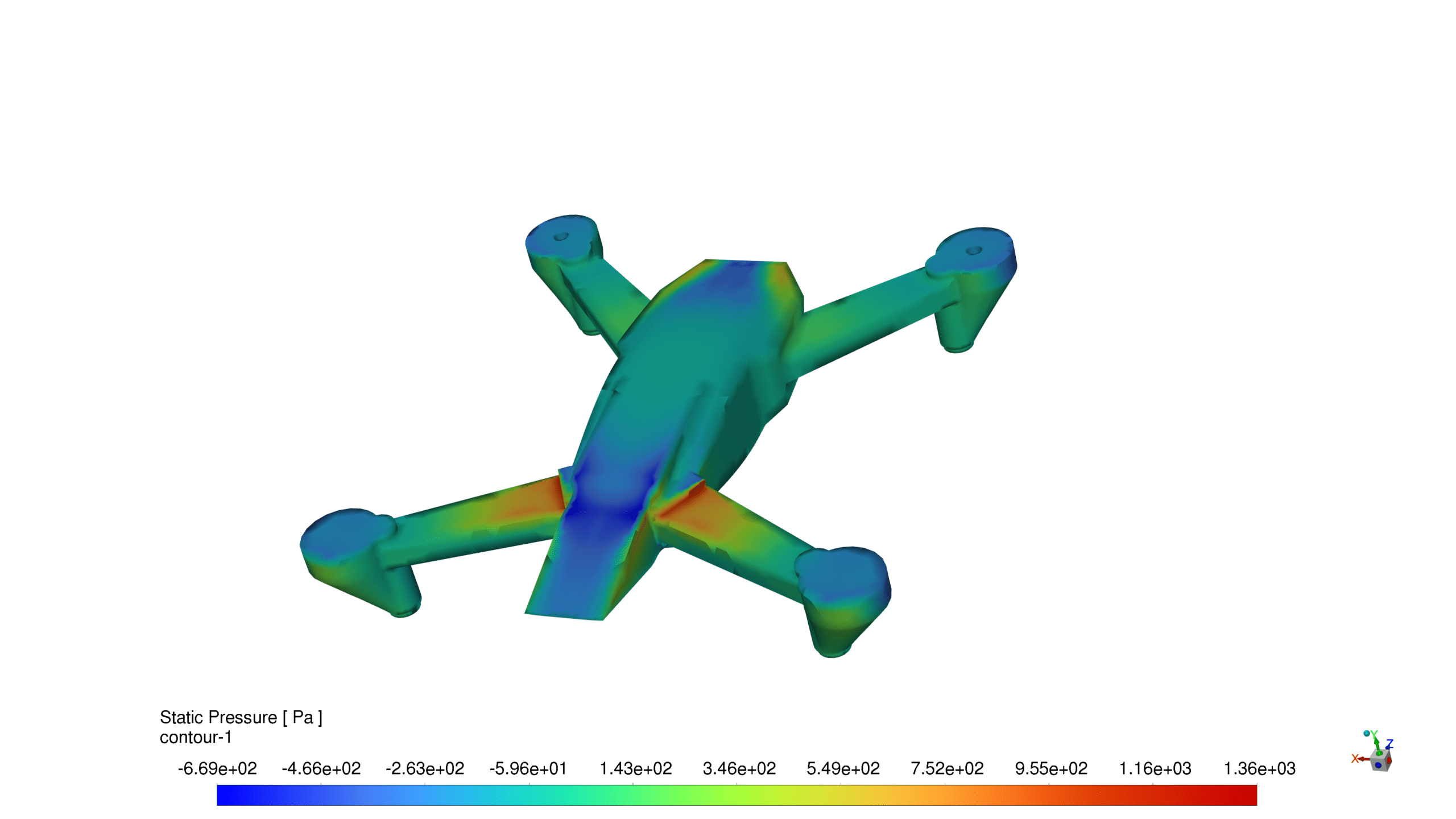
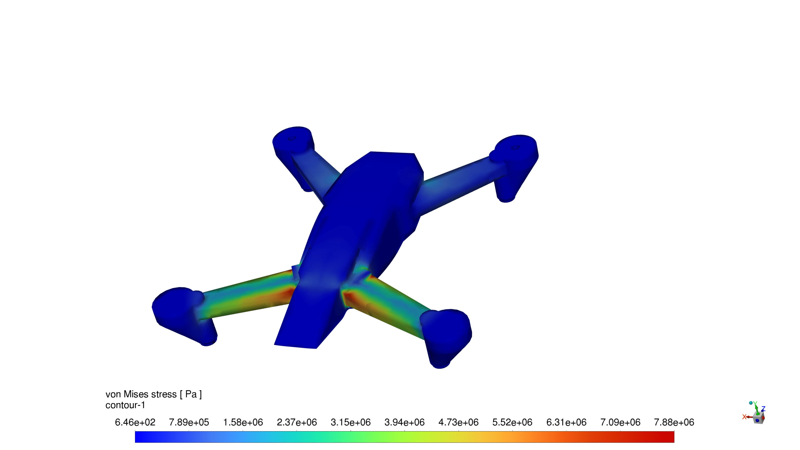
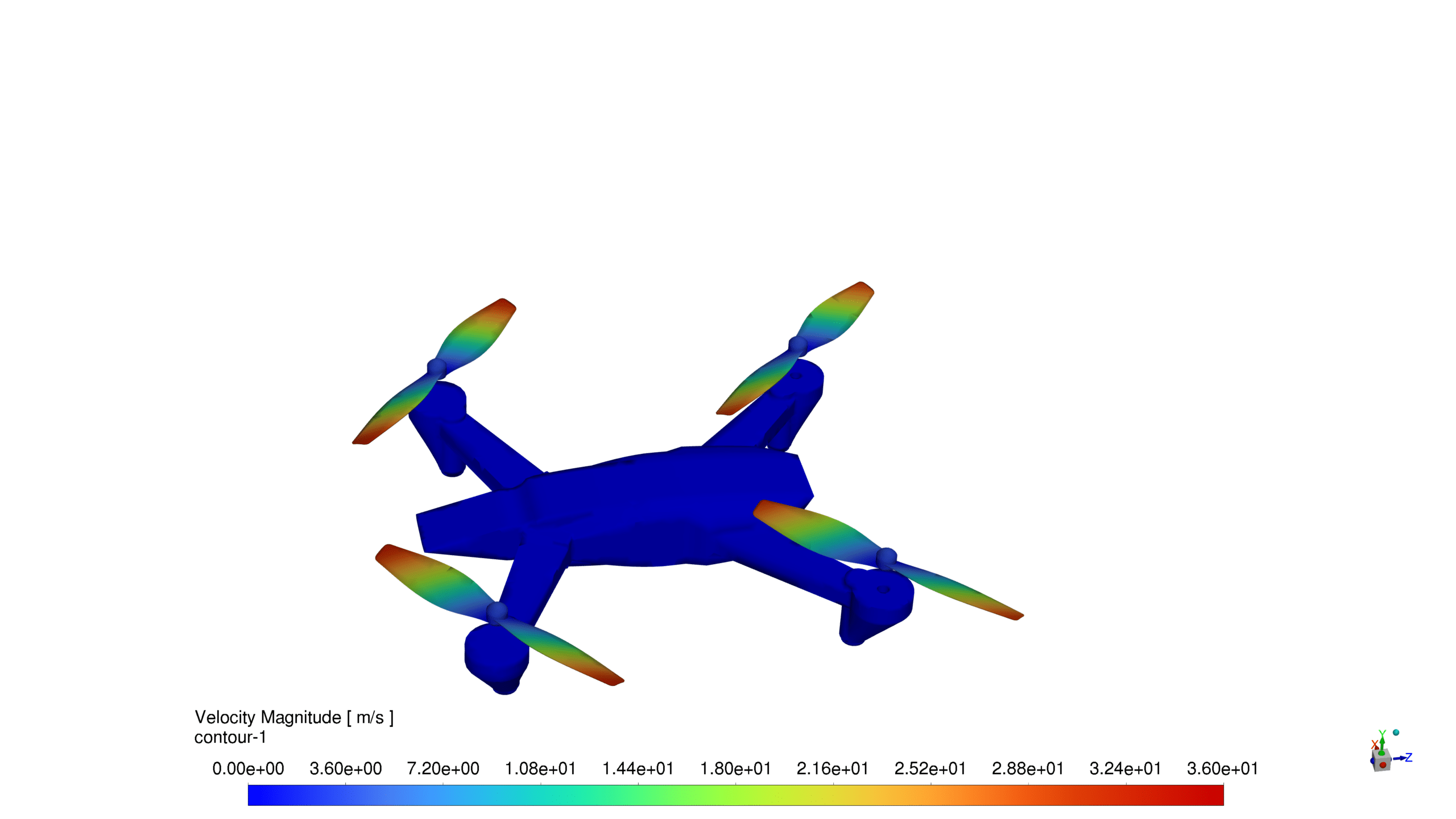
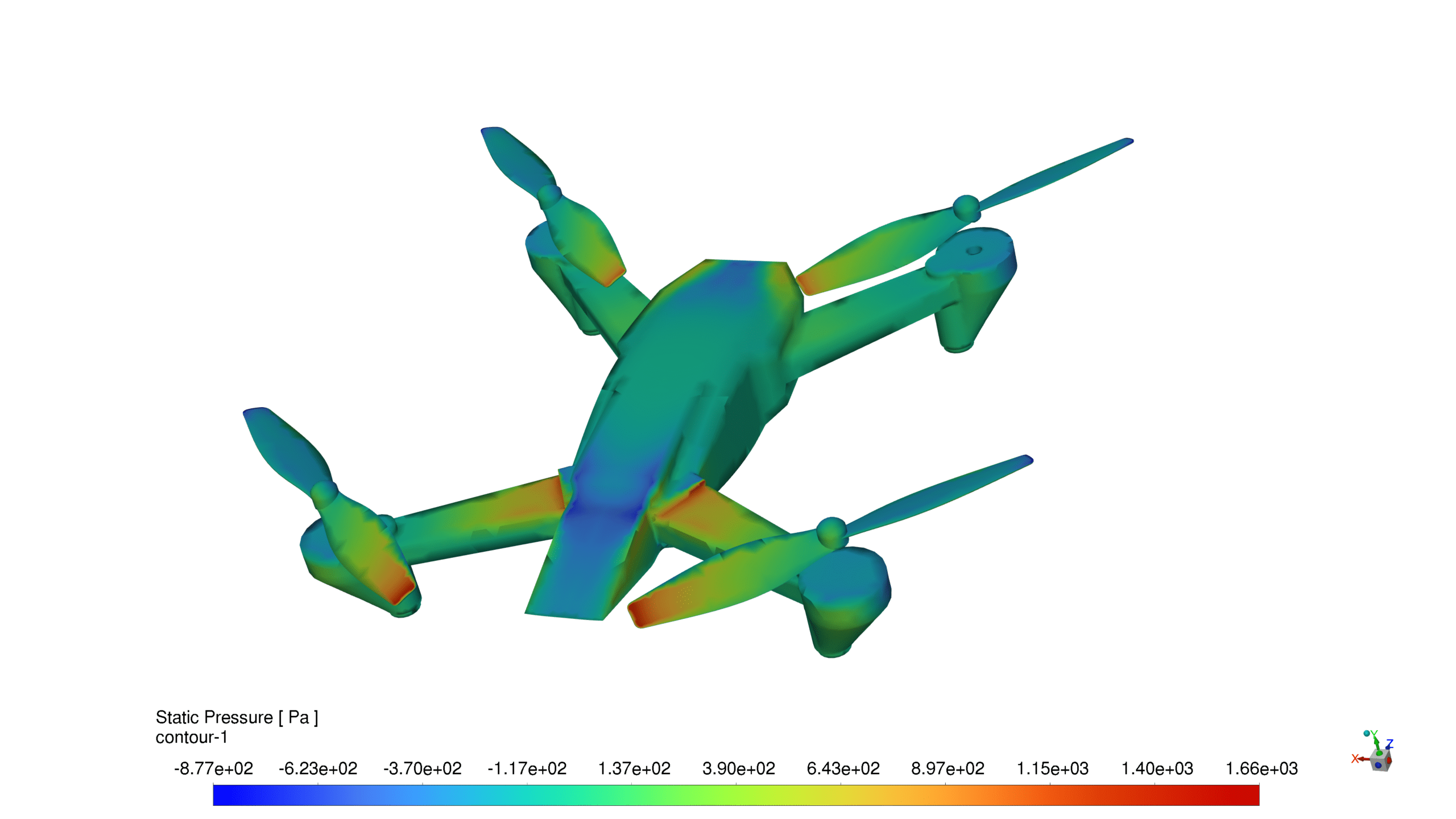
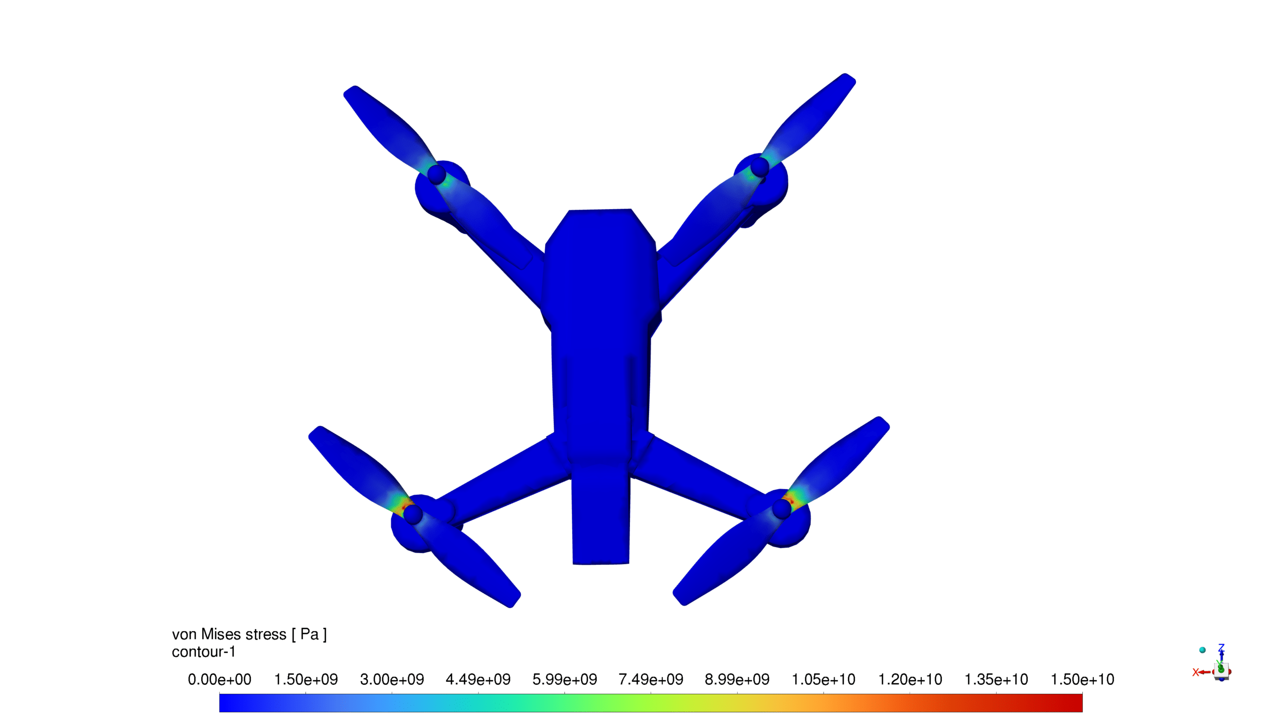
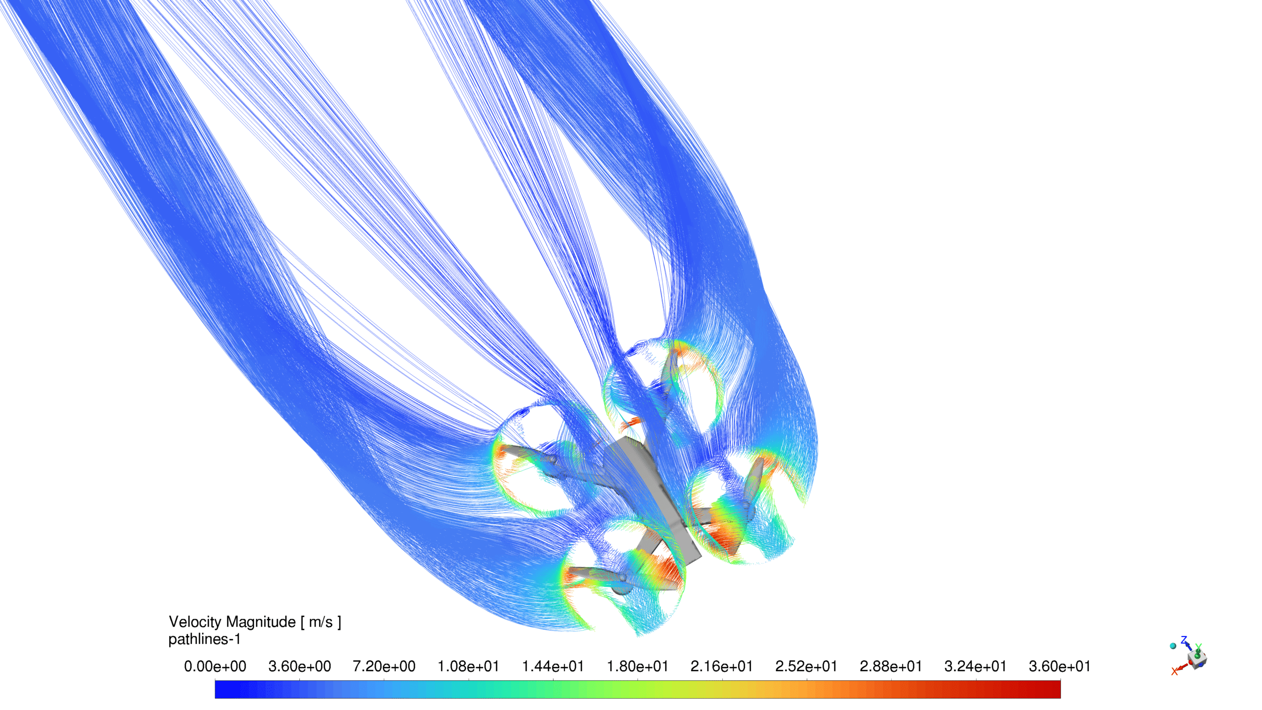
The contour plots depict the total displacement and von Mises stress distributions on the quadcopter structure.
In the first image, the total displacement contour reveals that the maximum displacement occurs at the tips of the quadcopter blades, reaching values around 0.115 m. The displacement gradually decreases towards the center of the quadcopter, with the main body experiencing minimal displacement. This distribution is expected due to the rotational motion of the blades and the aerodynamic forces acting on them.
The second image provides a closer view of the total displacement contour, focusing on the quadcopter blades. It confirms that the highest displacement values are concentrated at the blade tips, with a maximum value of approximately 0.339 mm. The displacement distribution along the blades appears to be relatively symmetric, indicating a balanced loading condition.
The third and fourth images present the von Mises stress contours on the quadcopter structure. The von Mises stress is a scalar value that combines the effects of all stress components and provides a measure of the overall stress state. In both images, the stress distribution shows higher stress values near the blade roots, where they connect to the quadcopter body. The maximum von Mises stress reaches around 150 MPa in the third image and approximately 78.8 MPa in the fourth image, suggesting that the stress levels are within the acceptable range for the material used.
The stress distribution along the blades exhibits a gradual decrease from the root to the tip, which is consistent with the expected stress pattern in rotating structures. The relatively low-stress values at the blade tips indicate that the design is well-optimized for the given operating conditions.
Overall, the FSI simulation results provide valuable insights into the structural behavior of the quadcopter under the influence of aerodynamic forces. The displacement and stress distributions can be used to assess the performance and integrity of the quadcopter design. The results suggest that the current design is capable of withstanding the loads experienced during operation, with no excessive deformations or stress concentrations observed.
Reviews
There are no reviews yet.