Sea Robot Motion Immersed in Water, Dynamic Mesh
$100.00 $50.00 Student Discount
- The problem numerically simulates Sea Robot Motion Immersed in the Water using ANSYS Fluent software.
- We design the 3-D model by the Design Modeler software.
- We mesh the model with ANSYS Meshing software, and the element number equals 30010.
- We perform this simulation as unsteady (Transient).
- We use the Dynamic Mesh model to apply the location displacement and the shape changes of computational cells.
Click on Add To Cart and obtain the Geometry file, Mesh file, and a Comprehensive ANSYS Fluent Training Video.
To Order Your Project or benefit from a CFD consultation, contact our experts via email (info@mr-cfd.com), online support tab, or WhatsApp at +44 7443 197273.
There are some Free Products to check our service quality.
If you want the training video in another language instead of English, ask it via info@mr-cfd.com after you buy the product.
Description
Sea Robot Motion Immersed in the Water, Dynamic Mesh, ANSYS Fluent Tutorial
In this project, the moving of a Sea Robot Motion Immersed in Water by the dynamic mesh method is simulated by ANSYS Fluent software. We perform this CFD project and investigate it by CFD analysis.
The present model is designed in two dimensions using Design Modeler software.
The meshing of the model has been done using ANSYS Meshing software. Moreover, the element number is 30010.
Also, the transient solver has been enabled due to the dynamic mesh option.
Robot Methodology
In problems where the location and shape of computational cells change, it is mandatory to use the dynamic mesh model to prevent the extreme deterioration of elements’ quality.
Smoothing and remeshing methods create higher-quality elements when the previous ones may cause errors and are no longer useful to perform calculations with. Remeshing occurs every 50 iterations to generate a new high-quality mesh.
The robot (cube) is first placed on the left side of the domain and moves toward the inlet boundary using an imposed velocity profile (velocity in the X-direction equal to 3 m/s for 0 to 3 seconds).
The standard k-epsilon model was used to solve the turbulent fluid equations. Also, the water enters the rectangular computational domain with a velocity of 1.5 m/s.
Robot Conclusion
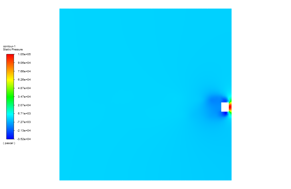
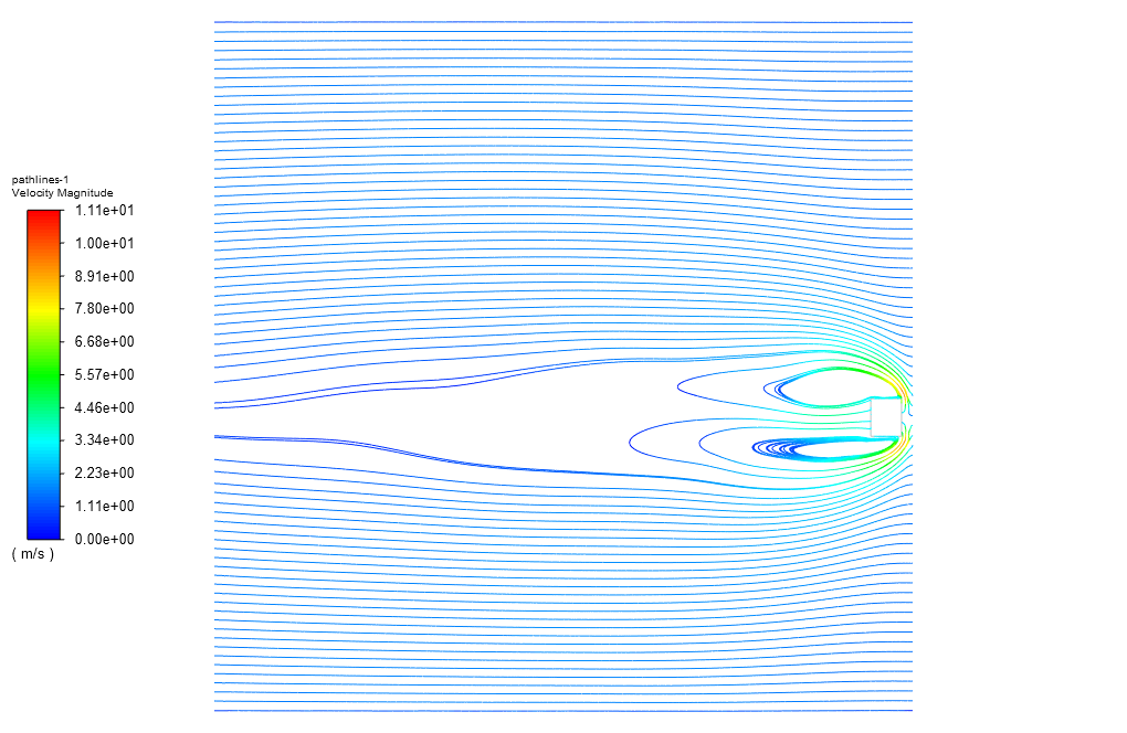
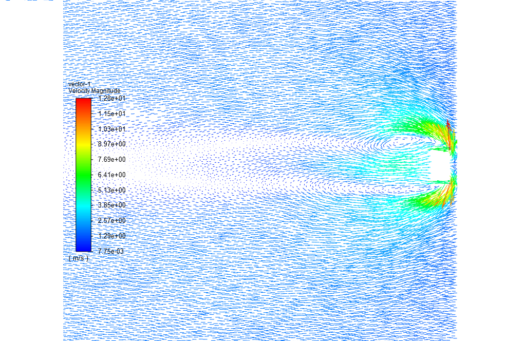
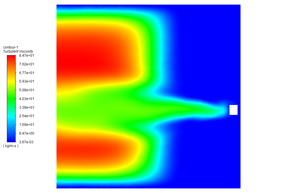
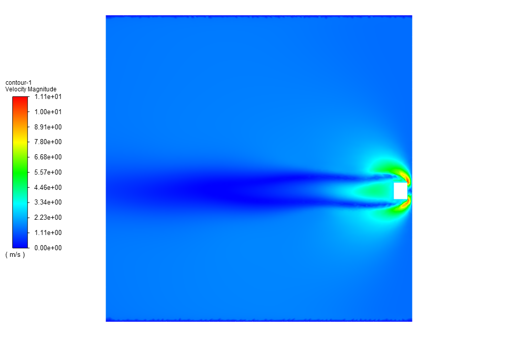
At the end of the solution process, two-dimensional contours related to the velocity, pressure, turbulent viscosity, and streamlines inside the computational domain are obtained.
The contours related to pressure clearly show how the robot’s motion against the water flow direction causes the pressure at the stagnation point to increase.
Furthermore, by viewing the contours related to velocity and streamlines, one can easily understand that the opposite motion of the robot concerning the water flow direction will give rise to the wake region occurring behind the robot.

Catharine Kling MD –
I am thrilled with how clearly the Sea Robot Motion simulation results were presented. The pressure contours and streamlines were particularly helpful in visualizing the stagnation points and wake regions.
MR CFD Support –
Thank you for your positive feedback! We’re delighted to hear that the simulation results were clear and informative for you. Understanding stagnation points and wake region is crucial for analyzing fluid dynamics, and we’re glad our product could aid in this visualization. We look forward to providing you with more valuable insights in future products!
Miss Jalyn Harvey DDS –
I’m thrilled with how this project visually explains how pressure changes occur when the sea robot moves against the water flow. The dynamic mesh approach seems key for accurately capturing the interaction between the robot and the water. Can you share more on how the dynamic mesh helped us analyze the wake region and the quality of elements after remeshing?
MR CFD Support –
Thank you for your positive feedback about the sea robot motion simulation! The dynamic mesh technique allows the mesh to update and adapt to changes in geometry or position that result from the robot’s motion in the water. To study the wake region effectively, it is essential that the mesh in that region maintains high quality and resolution. Therefore, by using smoothing and remeshing methods during the simulation, the solver generates higher-quality elements adapted to the new conditions every 50 iterations. This ensures that the mesh can accurately capture rapidly changing flow features behind the robot, like the formation of vortices in the wake region, without succumbing to errors due to deteriorating element quality.
Agnes Ryan –
Wonderfully comprehensive simulation of the Sea Robot motion. The dynamic mesh handling is particularly intriguing – from remeshing every 50 iterations ensuring high quality of elements to the turbulent models applied. I’m especially impressed by the way texture contours convey flow dynamics, such as the wake behind the robot.
MR CFD Support –
Thank you kindly for your appreciation! We are really glad to know that our in-depth simulation of the Sea Robot gripped your attention, and that you found the dynamic mesh technique and presentation of results through various contours to be informative and interesting.
Prof. Simeon Pfannerstill DVM –
I’m fascinated by the sea robot motion immersion simulation. Your product managed to depict the physics so realistically. The results leading to the wake region behind the robot helped solidify my understanding of fluid dynamics. Great job!
MR CFD Support –
Thank you for the wonderful feedback! We’re thrilled to hear that the Sea Robot Motion Immersion simulation in ANSYS Fluent was able to provide you with a clear and realistic depiction of the fluid dynamics involved. It’s always rewarding to know that our work can enhance understanding and contribute to learning in such a meaningful way.
Kane Emard –
I just completed this tutorial for Dynamic Mesh CFD on the Sea Robot, and the step-by-step guidance made the learning curve so manageable! Excellent material for someone looking to delve into motion simulation.
MR CFD Support –
Thank you for your fantastic review! We’re thrilled to hear that our Sea Robot Dynamic Mesh CFD tutorial met your learning needs and helped you effectively understand motion simulations. Your positive feedback motivates us to continue providing high-quality educational material. If you ever have more questions or need further assistance with your simulations, please don’t hesitate to reach out. Happy simulating!
Cynthia Rice –
The changes in contours of pressure and velocity clearly depict the effect of the Sea Robot’s movement through water. The dynamic mesh handling works wonders in illustrating complex interactions.
MR CFD Support –
Thank you so much for acknowledging the effectiveness of the dynamic mesh technique and the detail shown in the pressure and velocity contours. It’s great to hear that you found the simulation useful in understanding the sea robot’s interaction with water.
Chadrick Walsh –
After following this tutorial, my Sea Robot’s motion simulation is looking quite different from the expected outcome. Is there any chance that different versions of ANSYS Fluent impact these results significantly, assuming that all steps were correctly followed?
MR CFD Support –
It’s possible that different versions of ANSYS Fluent may introduce slight variations due to updates in solver algorithms or methodologies. However, if you’ve accurately followed all the steps, the results should be fairly consistent. Please ensure that the mesh quality is sufficient, all boundary conditions are correctly set, and the transient solver settings align with the tutorial guidance for the best possible accuracy.
Ms. Cecilia Schowalter –
The simulation of the sea robot moving through water sounds complex. Could you explain how the dynamic mesh method benefits this particular study?
MR CFD Support –
Certainly, the dynamic mesh method is essential for simulating problems where the geometry may move or deform during the simulation. In the case of the sea robot, as it moves through the water, the mesh around it needs to adjust dynamically to accommodate the changing geometrical position. Using the dynamic mesh allows for the continuous recalculations necessary for a CFD analysis to maintain accurate results without the mesh quality deteriorating. It’s especially beneficial for capturing fluid-structure interactions and for ensuring that the transient behaviors are correctly modeled.
George Toy PhD –
The dynamic mesh aspect has me curious—how does the software ensure mesh quality while the robot is in motion, and how does that impact computational resources?
MR CFD Support –
The software ensures mesh quality through the usage of dynamic mesh techniques like smoothing and remeshing. These ensure high-quality elements where remeshing especially offers new high-quality mesh generation when elements degrade due to motion. Smoothing adjusts mesh node positions to improve quality, while remeshing modifies the topology. To maintain computational efficiency, remeshing is set to occur periodically, every 50 iterations in this case, which balances computational resource demands with mesh quality.
Catalina Koepp –
I found the simulation of Sea Robot Movement particularly insightful. The dynamics were well-presented and the complex interactions vividly explained. Kudos to MR CFD for providing such a comprehensive tutorial!
MR CFD Support –
Thank you for your kind words! We’re thrilled to hear that you found our Sea Robot Movement simulation tutorial comprehensive and insightful. We strive to provide detailed explanations and high-quality simulations to aid in understanding complex interactions. Thanks for choosing MR CFD!
Waino Swaniawski –
I was fascinated by the contour results representing pressure increase at stagnation points and the wake region behind the moving robot. Could you provide more insight regarding the precise benefits that this simulation offers for practical sea robot design and operation?
MR CFD Support –
Thank you for your kind words! Advanced simulations like these provide invaluable insight for sea robot design and operation. Specifically, they help engineers understand hydrodynamic forces and predict robot behavior under various underwater conditions. These insights can lead to optimized designs for improved energy efficiency, reduced drag, and enhanced maneuverability, all of which contribute to the robotic system’s overall operational efficacy and longevity.
Burnice Erdman –
This sea robot simulation is exceptionally detailed and provides great insight into the behavior of the robot when immersed in water. The use of dynamic mesh to simulate its motion is ingenious, perfectly addressing the challenges of moving bodies in a fluid environment. The iterations for remeshing to ensure accuracy are impressive, as are the use of the k-epsilon turbulence model and the clear contour presentations which situate us within the computational domain effectively. Really admirable work on visualizing the pressure changes and disturbed water flow due to the robot’s motion. It eloquently illustrates not just the science but the underlying fluid dynamics artfully.
MR CFD Support –
Thank you so much for the positive feedback! We’re thrilled to hear that you found the simulation details and visualization so enlightening and appreciative of the dynamics involved. Understanding the intricate behavior of submerged motion and its corresponding impacts on the flow and pressure is critical, and we’re glad this was clearly conveyed through our sea robot simulation. Your comments inspire us to continue delivering high-quality simulations and tutorials.