Rough Surface Heat Transfer CFD Simulation, Training
Free
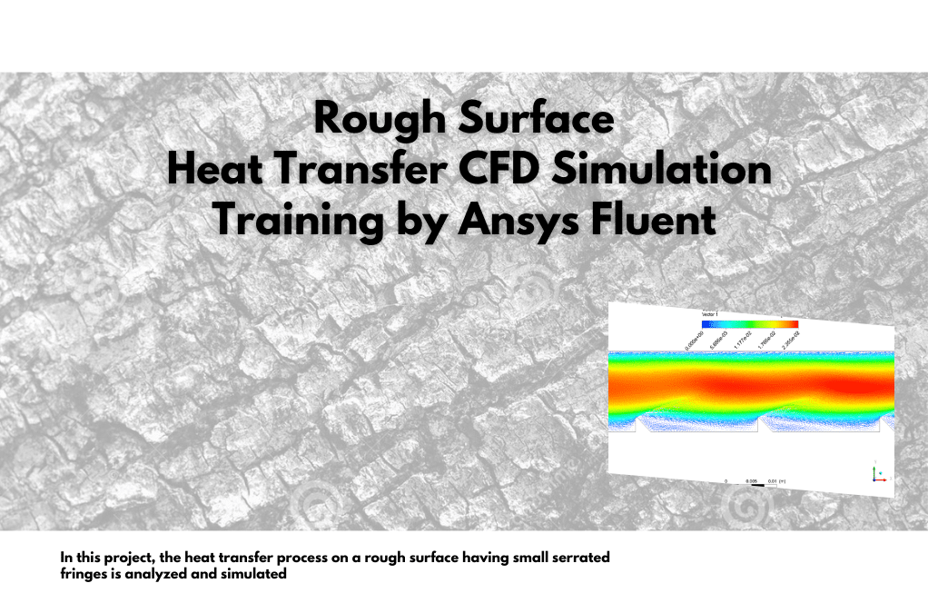
In this project, the heat transfer process on a rough surface having small serrated fringes is analyzed and simulated.
Click on Add To Cart and obtain the Geometry file, Mesh file, and a Comprehensive ANSYS Fluent Training Video.To Order Your Project or benefit from a CFD consultation, contact our experts via email (info@mr-cfd.com), online support tab, or WhatsApp at +44 7443 197273.
There are some Free Products to check our service quality.
If you want the training video in another language instead of English, ask it via info@mr-cfd.com after you buy the product.
Description
Rough Surface, Heat Transfer CFD Simulation, ANSYS Fluent Training
In this project, the heat transfer process on a rough surface having small serrated fringes is analyzed and simulated by ANSYS Fluent software. The water flow enters the channel with a velocity of 0.0134 m/s, and since the water flow does not have a high Reynolds number, the Laminar model was used to solve fluid flow equations. The energy model is also exploited to calculate the temperature distribution inside the computational domain.
Rough Surface Geometry & Mesh
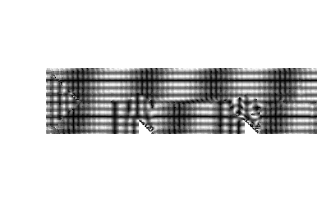
The geometry of this project is designed in ANSYS design modeler and meshed inside ANSYS meshing software. The mesh type used for this geometry is structured and the total number of elements is 102694.

CFD Simulation Settings
The critical assumptions considered in this project are:
- The present simulation and its results are considered steady and do not change as a function of time.
- The effect of gravity has been taken into account and is equal to -9.81 in the Y direction.
The applied settings are recapitulated in the following table.
| (rough surface) | Models | |
| Viscous model | Laminar | |
| Energy | on | |
| Boundary conditions | ||
| Inlet | Velocity inlet | |
| Inlet | 0.0134 m/s | |
| Temperature | 300 K | |
| Outlet | Pressure outlet | |
| Gauge pressure | 0 Pa | |
| Walls | Stationary wall | |
| Wall | Heat flux | 1000 W/m2 |
| Wall-surface-body | Heat flux | 0 W/m2 |
| (rough surface) | Solution Methods | |
| Pressure-velocity coupling | SIMPLE | |
| Spatial discretization | Pressure | Second order |
| Momentum | second order upwind | |
| energy | second order upwind | |
| Initialization | ||
| Initialization method | Standard | |
| gauge pressure | 0 Pa | |
| Velocity (x,y,z) | (0.0134,0,0) m/s | |
| Temperature | 300 K | |
Rough Surface Results & Discussion
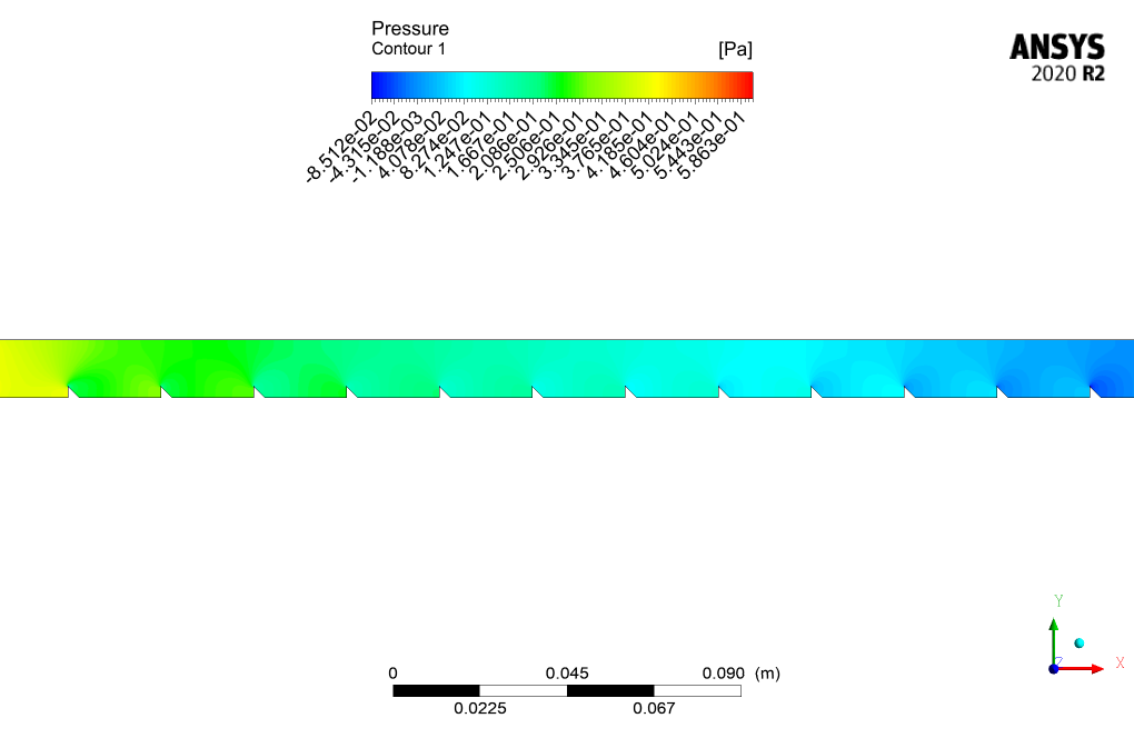
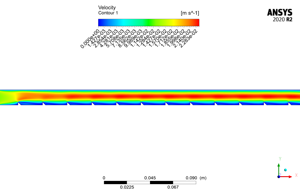
We present different contours of velocity, pressure, temperature, etc. after the simulation process and discuss in the following .
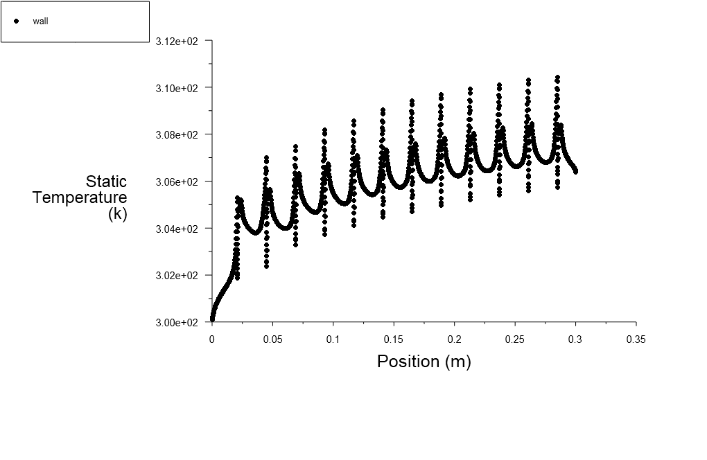
As shown in the temperature contour, the fluid temperature has increased after passing over the lower wall’s serrated fringes. These fringes have the role of changing fluid flow regime from Laminar to turbulent for purposes like increasing the total heat transfer.
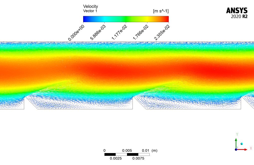
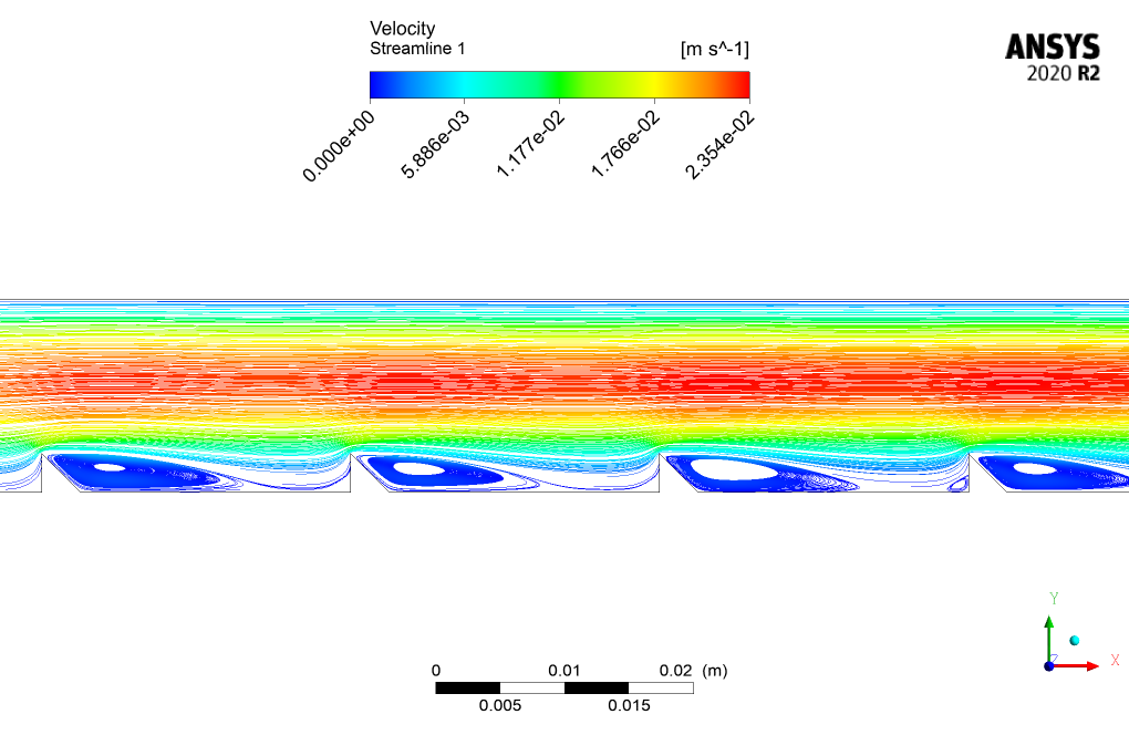
As previously discussed, fringes’ role in the velocity vector and streamlines contour shows that vortices are generated after the fluid flow has passed over the fringes. In other words, the fluid flow becomes turbulent after the fringes, causing the generation of vortices, and as we all know, the heat transfer coefficient is more than that of the laminar flow.



Reviews
There are no reviews yet.