Self-Propelled Submarine Motion, Dynamic Mesh (6-DOF)
$330.00 $165.00 Student Discount
- The problem numerically simulates Self-Propelled Submarine Motion using ANSYS Fluent software.
- We design the 3-D model with the CATIA software.
- We Mesh the model with ICEM software, and the element number equals 2802219.
- We perform this simulation as unsteady (Transient).
- We use the Dynamic Mesh method to define grid changes.
- We use a UDF to define the movement as a Rigid Body.
- We use the VOF Multi-phase model to consider water and air.
To Order Your Project or benefit from a CFD consultation, contact our experts via email (info@mr-cfd.com), online support tab, or WhatsApp at +44 7443 197273.
There are some Free Products to check our service quality.
If you want the training video in another language instead of English, ask it via info@mr-cfd.com after you buy the product.
Description
Description
The present problem simulates the motion of a self-propelled submarine floating on the water surface by dynamic mesh method using ANSYS Fluent software.
This product is the fourth chapter of the Dynamic Mesh Training Course.
In this simulation, a computational domain considering air and water with a certain level is designed; So that a self-propelled submarine is floating on the surface of the water.
We design the present model in three dimensions using AutoCAD, CATIA, and ICEM software. The horizontal length of the submarine is 16.25 m, and at its end, there are several impellers with a diameter of 0.825 m.
Around the submarine, we design a cylindrical computational area inside a cubic area as the total computational domain. We carry out the meshing using ICEM software.
The mesh type is hybrid (a combination of structured and unstructured); Thus, meshing in areas close to the submarine hull is unstructured and generally structured areas of the model. Also, the element number is equal to 2802219.
Self-Propelled Submarine Methodology
In such models, the location of the cells in the grid changes due to the displacement of their adjacent boundaries over time. Therefore, we benefit from the dynamic mesh model to define the instantaneous grid shift.
Initially, a self-propelled submarine was designed for this simulation, and three computational zones were created around the submarine. In determining dynamic mesh methods, smoothing and remeshing methods have been used.
Six degrees of freedom (six-DOF) have also been used to define the type of dynamic mesh behavior; This means that the model can move and relocate at six degrees. The properties of six degrees of freedom, including the mass and the moment in different directions for this model, are defined as a UDF.
To define areas with dynamic mesh, the body or walls of the submarine itself are defined as a Rigid Body. A small cylindrical area around the submarine is defined as a rigid body. And then, around this cylindrical region, a larger cubic area of the Deforming type is defined.
This means that the submarine and a limited area around it act as a rigid and integrated body and can be moved in a transitional or rotational manner without any change in meshing.
It should be noted that in the section related to the Rigid Body, the spatial coordinates of the submarine center of gravity should be defined, as well as its position in the model. The submarine is defined as floating on the water’s surface.
The volume of fluid (VOF) multiphase flow model should be used. So that in the upper part of the computational area, air and the lower part, water are defined. Both phases flow at a speed equal to 1.62 m/s in the horizontal direction (X-axis) and exit at a pressure equivalent to atmospheric pressure.
The open channel condition is used at the output to define the water level. It is assumed that the free water level at the outlet of the computational area is equal to 1.084824 m, and the height of the floor is equal to -100 m.
Due to the main nature of the model based on the use of dynamic mesh, the solver simulation should be defined as Transient. The present model performs the simulation process in 10 seconds with a time step size of 0.001 seconds.
Self-Propelled Submarine Conclusion
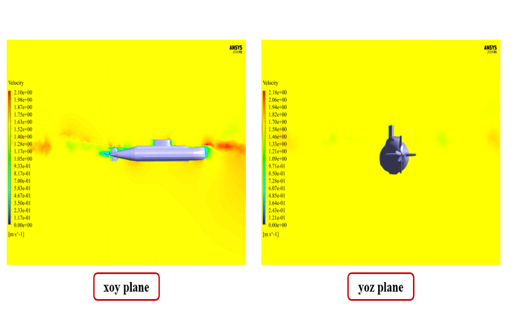
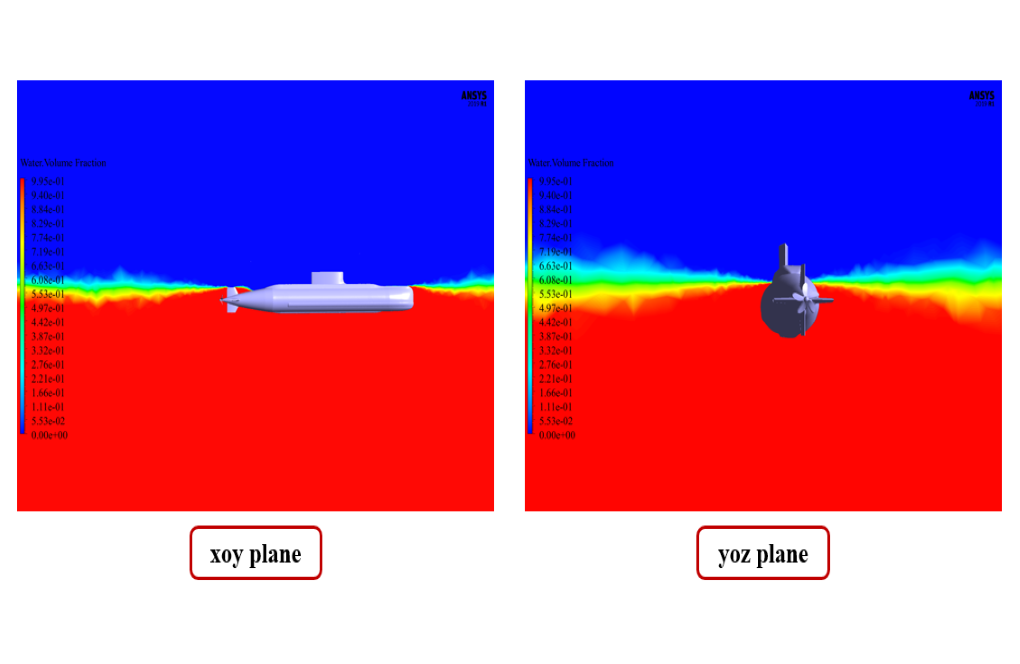
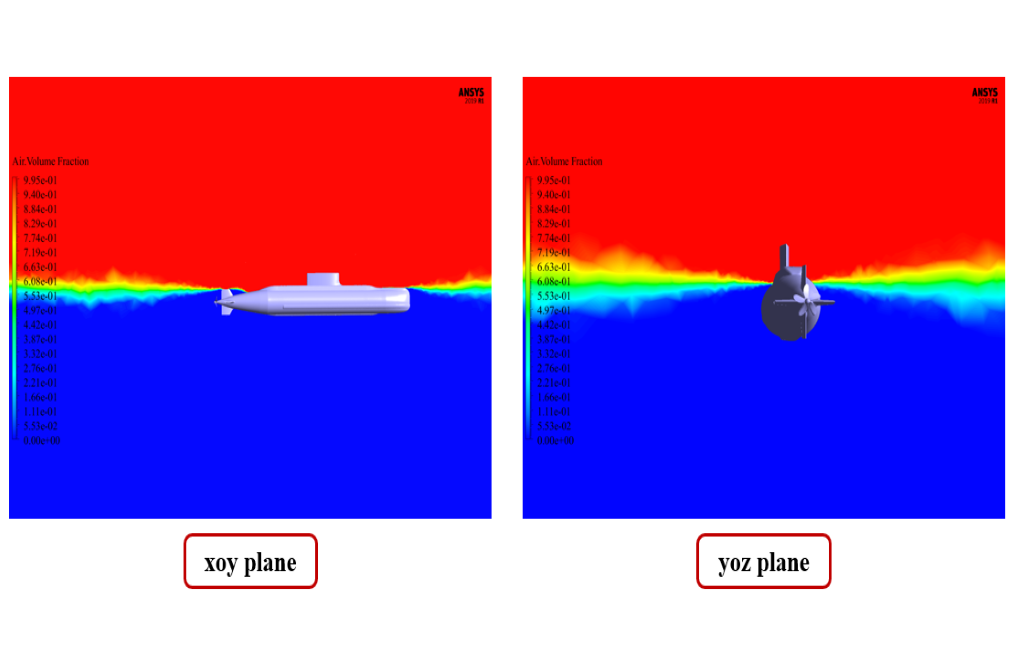
At the end of the solution process, we obtain two-dimensional contours related to the velocity and volume fraction of each air and water phase in the floating submarine areas.
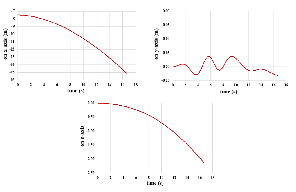
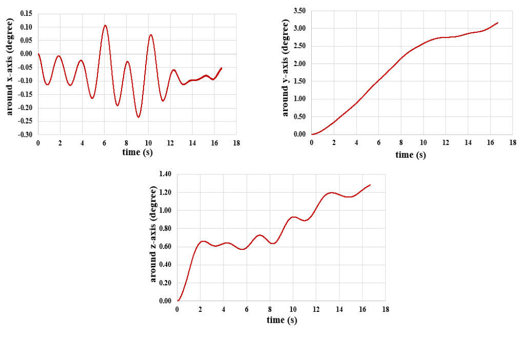
We present these contours in two planes, X-Y and Y-Z, and in the last second of the simulation process. Also, we show the diagram of the amount of submarine transitional and rotational movement in the direction of all three axes, X, Y, and Z.
Kaleigh Raynor –
Can this simulation be used to estimate the aerodynamic noise generated by the fan stage?
MR CFD Support –
While the current simulation does not directly estimate the aerodynamic noise, it can provide valuable insights into the flow structures that contribute to noise generation.
WU CHEN YUAN –
Thank you! This case is very interesting
Hans Schneider –
How does the simulation model the flow separation from the fan blades?
MR CFD Support –
The simulation models the flow separation from the fan blades using the turbulence model, which captures the onset and development of flow separation.
Amaya Kozey –
How does the simulation account for the boundary layer development along the fan blades?
MR CFD Support –
The simulation accounts for the boundary layer development along the fan blades using the wall functions in the turbulence model, which provide a good approximation of the boundary layer behavior.