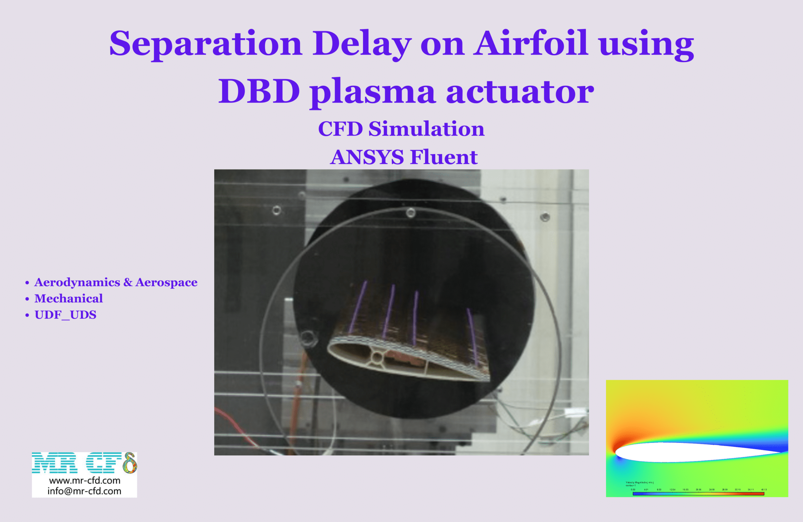
Separation Delay on Airfoil Using DBD plasma actuator, ANSYS Fluent
$150.00 $75.00 Student Discount
- In this project, the electrical current caused by the electrical potential is modeled using ANSYS Fluent.
- Also, the magnetic field created by the electrical current and its body force is simulated.
- Three User-Defined Scalars (UDS) are added for calculating the electrical and magnetic properties, and five User-Defined Functions (UDF) are used for the computation of the magnetic equations’ source terms, heat release from the electric field, and momentum body forces.
- The geometry was created in SpaceClaim, and a mesh consisting of 463,701 elements was generated using ANSYS Meshing.
- The improvement of the flow field in terms of separation on an airfoil NACA 0012 was investigated by using plasma at two velocities and angles of attack.
To Order Your Project or benefit from a CFD consultation, contact our experts via email (info@mr-cfd.com), online support tab, or WhatsApp at +44 7443 197273.
There are some Free Products to check our service quality.
If you want the training video in another language instead of English, ask it via info@mr-cfd.com after you buy the product.
Description
Description
The separation of flow from the suction side of airfoils leads to reduced lift force and increased drag, and in extreme cases, can cause the airfoil to stall. This separation is caused by the loss of boundary layer energy, resulting in detachment from the airfoil’s surface. In this project, we aim to simulate a solution to this issue; in other words, we will simulate the plasma created by a Dielectric Barrier Discharge (DBD) actuator and the body force of the magnetic field on it, which increases the energy of the boundary layer flow and prevents separation.
A DBD is an active controller that can enhance the flow field without any moving parts. A high voltage difference between the cathode and anode ionizes the air, converting it into plasma form, which can establish an electrical current between the cathode and anode. This current creates a magnetic field. The magnetic field then acts on the ions of the air, adding momentum to the boundary layer and preventing separation.
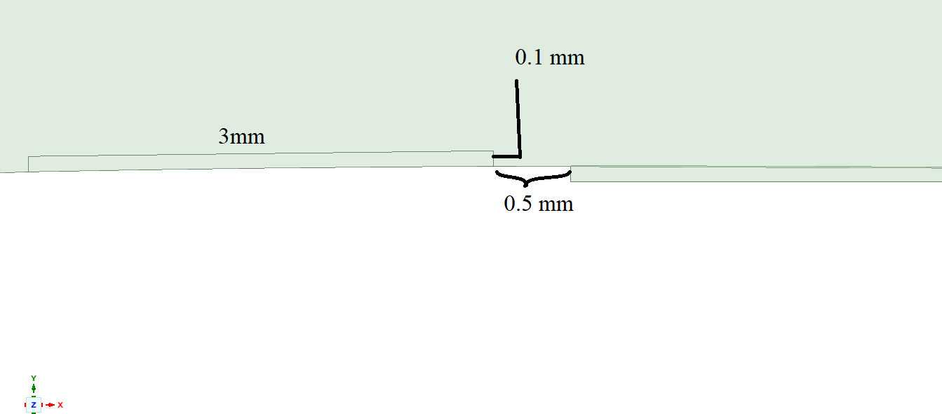
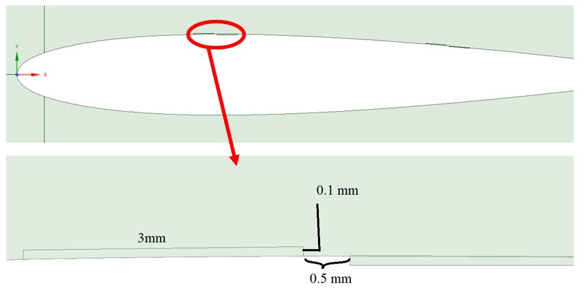
In this project, we use a NACA 0012 airfoil with a chord length of 0.1m. Two cases are modeled: the first with a flow velocity of 50 m/s and a 15-degree angle of attack, and the second with a flow velocity of 20 m/s and a 12-degree angle of attack. Two DBD actuators are located on the airfoil, one near the point of maximum thickness and the other near the trailing edge. The cathode voltage is set at 40 kV, and the anode voltage is 0 V. The geometry and dimensions of the DBDs are presented in the following figure.
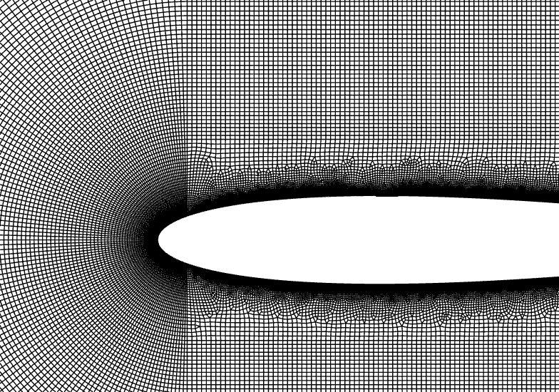
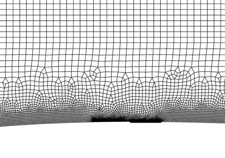
The geometry is designed in SpaceClaim® and meshed using ANSYS Meshing®. The mesh type is structured, with the element count being 463,701.
Methodology
In this simulation, the k-ε model was chosen for modeling the turbulence of the flow due to its accuracy and low computational cost. The Energy equation is also activated.
To simulate electricity and the magnetic field, we add 3 User-Defined Scalars (UDS). In this problem, the scalar for the first equation represents voltage or electrical potential (V), and the x and y components of the magnetic vector potential (Ax and Ay) are scalars for the second and third scalar equations. As we know, it does not have a mass flow flux. The steady-state transport equations of the scalars (V, Ax, and Ay) are presented below:
We add the second term in the transport equations of the magnetic field as a source term using a User-Defined Function (UDF). In the first relation, k is the electrical diffusion coefficient of ionized air and we consider it 0.5, and μ₀ is the magnetic permeability, which in this simulation we consider to be 1.2566*10⁻4 for air. Jₓ and jᵧ are the x and y components of current flow density that can be computed with the following formula:
In this formula, J represents the vector of current density. To couple with the energy equation and momentum equations, three source terms are added to the equation of energy, x-momentum, and y-momentum respectively as follows:
B is the magnetic induction vector and can be computed with the following formula:
5 User-Defined Functions (UDFs) are written and interpreted in Fluent based on the above formulations for the x and y components of magnetic scalar equations, energy source term, x-momentum, and y-momentum source term. We also use User-Defined Memory (UDM) to obtain the current vector directly from the UDF code, which can be analyzed in the post-processing step.
Also, air density is modeled as an ideal gas.
Results
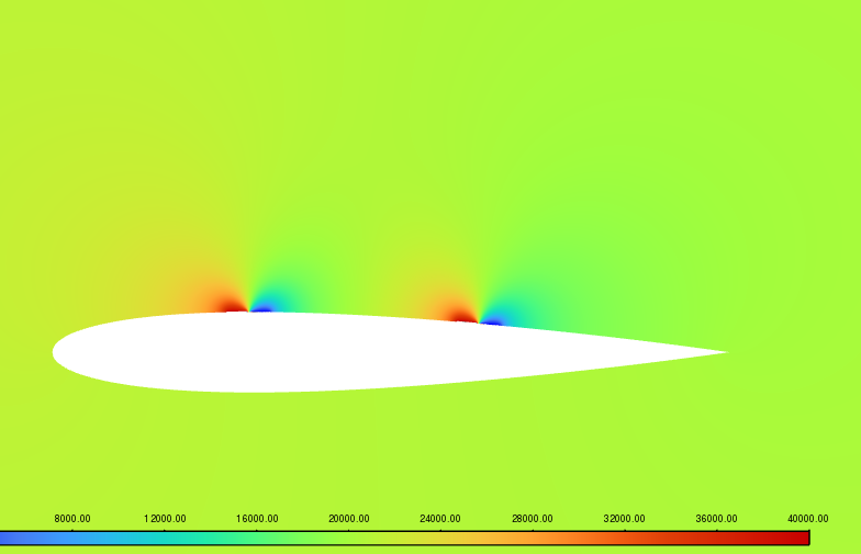
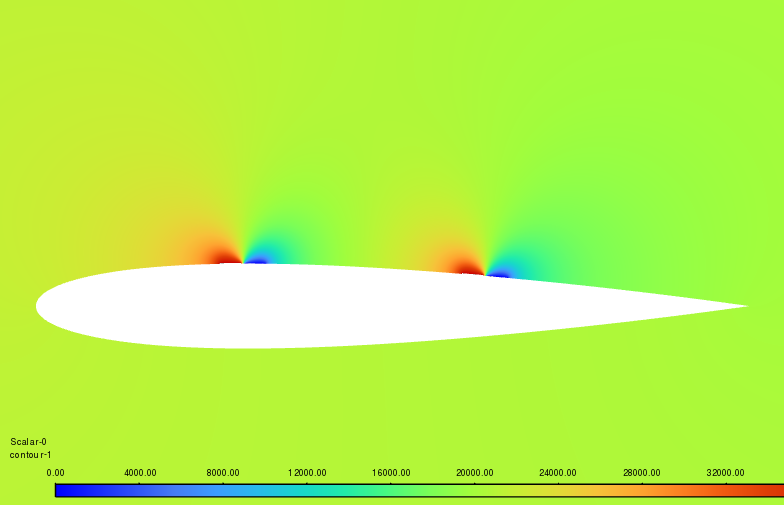
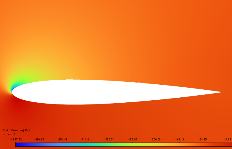
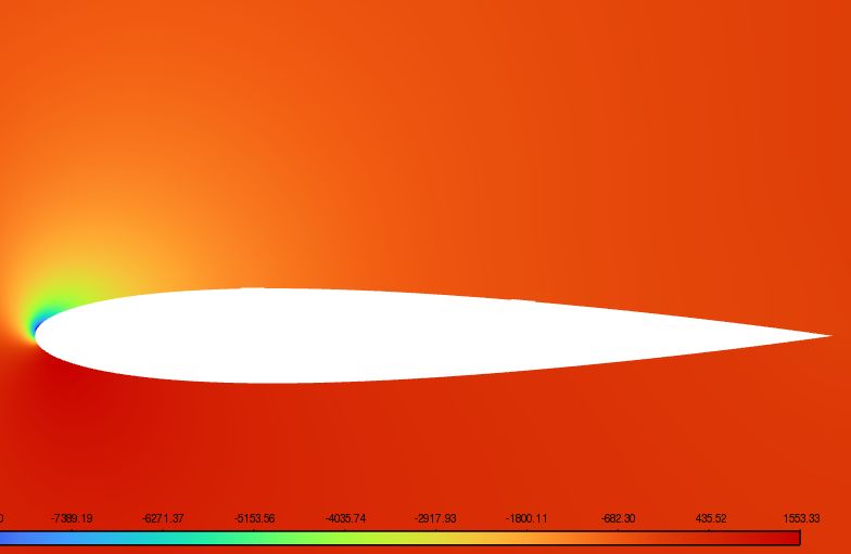
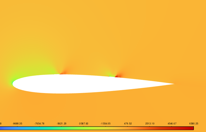
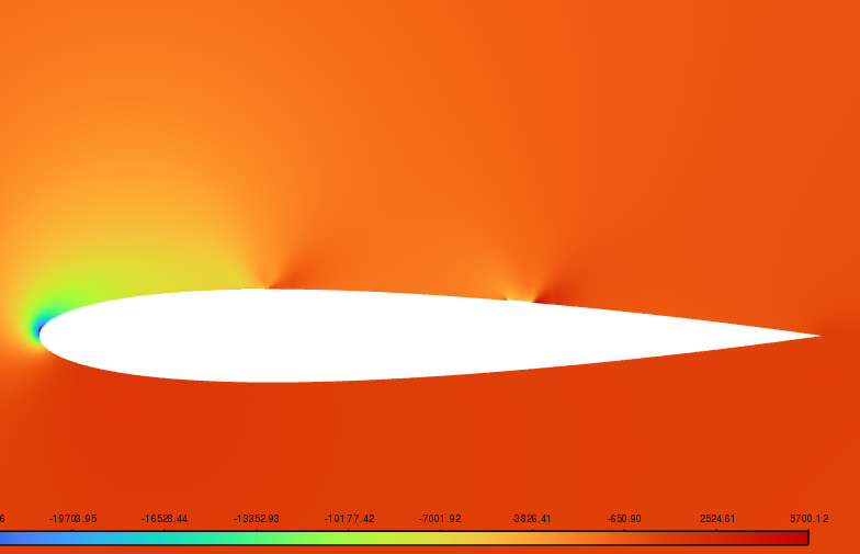
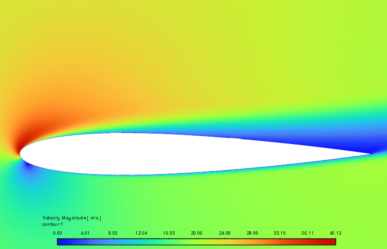
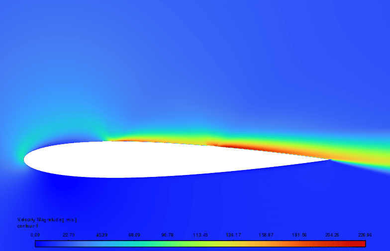
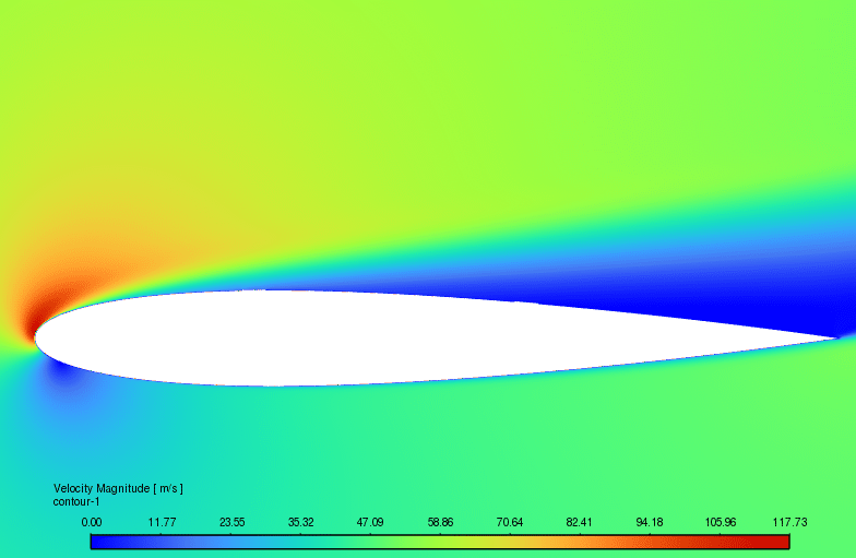
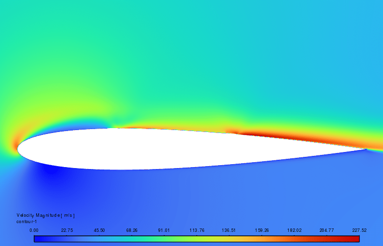
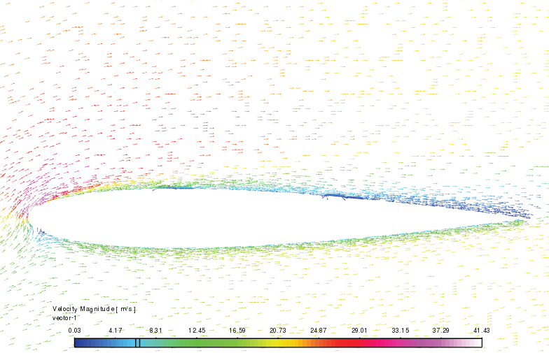
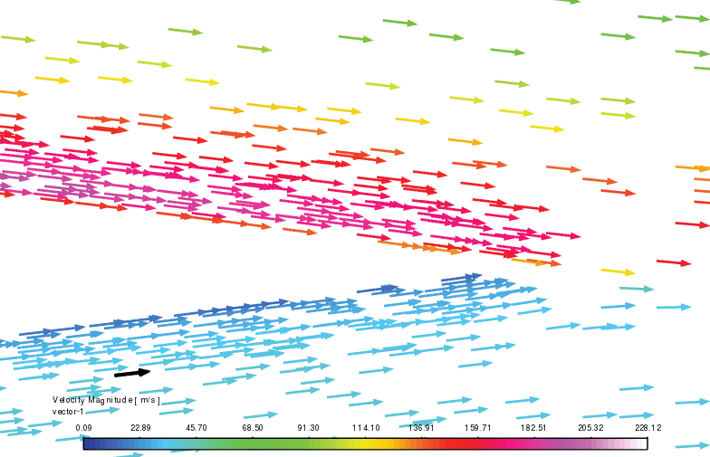
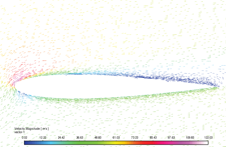
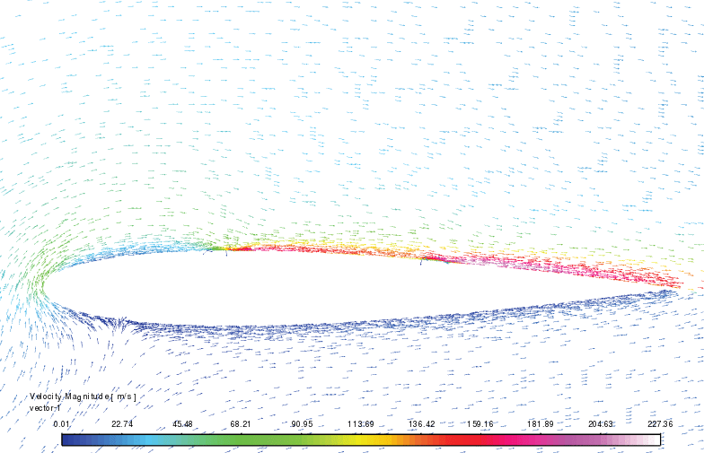
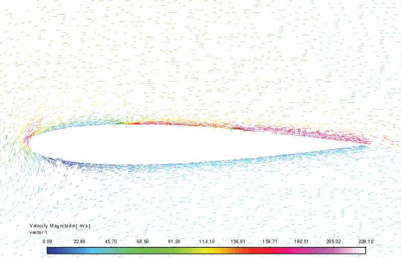
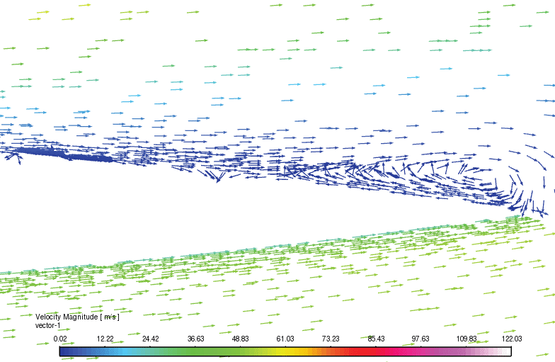
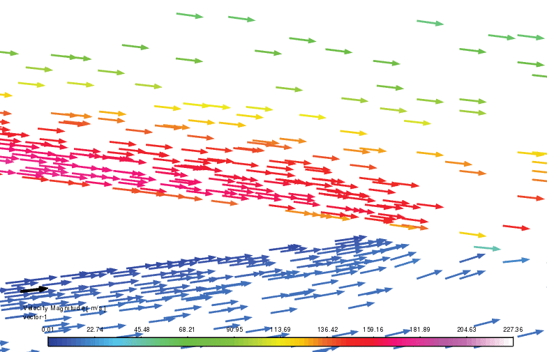
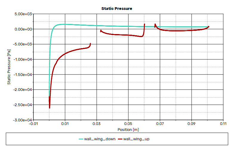
Contours of velocity and pressure around the airfoil as well as velocity vectors in all cases are presented and shows that plasma can improve the separation issues.
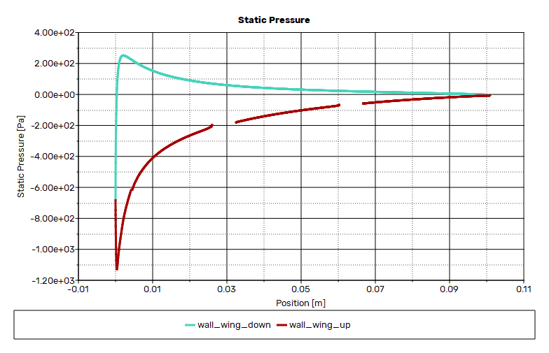
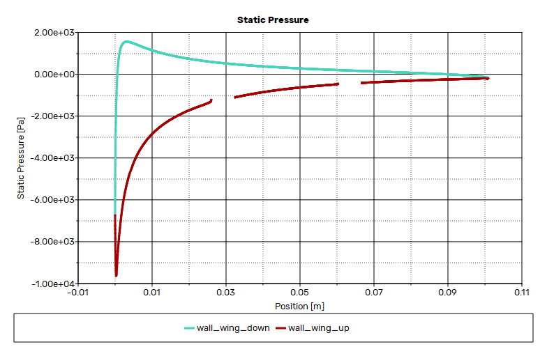
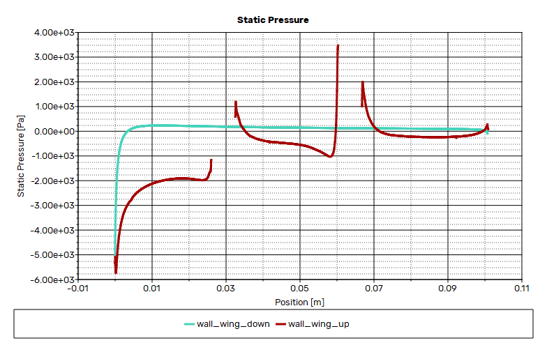
Results of lift coefficients as well as pressure plot along airfoil are summarized in the following table.
Related products
-
HAWT (Horizontal Axis Wind Turbine) ANSYS Fluent CFD Simulation Training
Rated 4.00 out of 5$140.00$70.00 Student Discount





Reviews
There are no reviews yet.