Sloshing Tank, ANSYS Fluent CFD Simulation Training
$330.00 $165.00 Student Discount
- The Sloshing fluid CFD simulation in a tank containing LNG fuel and air by ANSYS Fluent software.
- The geometry of the 2-D tank is modeled by Design Modeler software.
- A structured mesh is done for the sloshing tank by ANSYS Meshing software.
- The simulation is Transient.
- The Frame Motion (MRF) method applying a UDF for the sloshing movement is used.
- The Multiphase VOF model is applied to model the air and fluid.
Click on Add To Cart and obtain the Geometry file, Mesh file, and a Comprehensive ANSYS Fluent Training Video.
To Order Your Project or benefit from a CFD consultation, contact our experts via email (info@mr-cfd.com), online support tab, or WhatsApp at +44 7443 197273.
There are some Free Products to check our service quality.
If you want the training video in another language instead of English, ask it via info@mr-cfd.com after you buy the product.
Description
Sloshing
Experimental and numerical studies show the importance of the effect of fluid sloshing within the tank on the maneuverability of the floating devices like ships, boats, and so on. Among the most important laboratory studies, we can point:
1- Measuring the sloshing dynamics of a tank
2. Experimental-Statistical Study of Sloshing Wave Impact Loads in the Shell Tank Model
3. Verification of numerical sloshing results of the floating device containing natural gas tank using an experimental result on a two-dimensional section of the reservoir at a scale of 0.1 at two different filling heights.
4. Investigate the maximum long-term sloshing pressures applied to the shell tank in order to consider the effects of the vibration caused by the bump.
5- Experimental study of pressure distribution due to the liquid sloshing in a rectangular tank
Tank Geometry
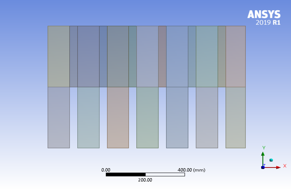
The initial stage of any simulation is devoted to the design of solution geometry or computational domain modeling. The computational domain in Sloshing CFD simulation is a tank containing LNG fuel and air. The tank uses several series of joints and inner walls to prevent fluid movement. This results in less friction of the fluid layers over each other, as the inertia of the fluid moving inside the tank can have an effect on the fuel carrier vehicle. The model of the 2-D tank is modeled by Design Modeler software. The tank geometry is 1 m long and 0.7 m wide. Six rows of 0.35 m high and 0.04 m thick were used to separate the fluid layers. The geometry is divided for structured mesh applications.
 Mesh
Mesh
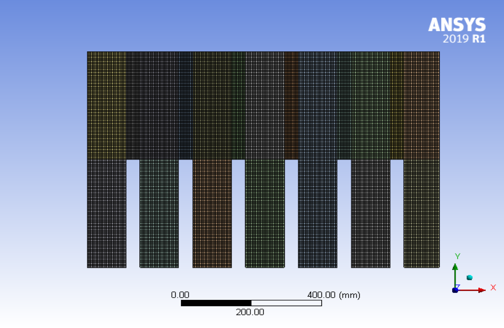
Since ANSYS Fluent software uses the finite volume method, it is important to have a high quality mesh. A structured mesh is done for sloshing tank by ANSYS Meshing software.
CFD Simulation
Once the mesh is loaded onto the ANSYS Fluent software, the solution process begins. This process involves defining the problem to the software. This table is a summary of Sloshing Tank CFD Simulation.
| Solver settings (sloshing tank): | |
| Type: | Pressure-based |
| Velocity formulation: | Absolute |
| Time setting: | Transient : Time-step : 0.005 s |
| Gravity: | On : -9.81 m/s2 in Y-direction |
| Energy: | off |
| Zone: | Frame Motion
UDF #include “udf.h” DEFINE_ZONE_MOTION(NEWMOTION,omega,axis,origin,velocity,time,dtime) { N3V_D (velocity,=,0.5*sin(10*time),0.0,0.0); N3V_S(origin,=,0.0); /* default values, line could be omitted */ N3V_D(axis,=,0.0,0.0,1.0); /* default values, line could be omitted */ } |
| Boundary conditions: | Walls: No-slip |
| Operating Condition: | Reference Pressure Point:
X : 0.00 m Y : 0.25 m Gravity: On : -9.81 m/s2 in Y-direction |
| Solution methods for sloshing CFD simulation: | SIMPLE |
| Pressure interpolation scheme: | PRESTO |
| Momentum: | QUICK |
| Level set implementation: | QUICK |
| VOF implementation: | Compressive |
| Relaxation: | Default |
| Initialization: | Standard All Zero
Patch: Region X: -10 m to +10 m Y: 0 to 0.25 m Pressure static: Rhow*g*(1-y/Hw) Water VF: 1.0 |
Multi-phase (sloshing tank) : |
|
| VOF : | Enabled |
| Formulation: | Implicit |
| Interface Modeling: | sharp |
| Implicit Body Force: | On |
| Open channel flow: | Off |
| Level Set | On |
| Phase-Interaction (sloshing tank): | |
| Surface tension Coeff (air-water): | 0.0725 n/m |
| Material used for sloshing tank CFD simulation : | |
| Fluid: | Air : Primary phase
Water : Secondary phase |
| Monitor : | Point: Static Pressure: 0.0525 m |

 Mesh
Mesh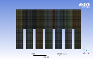


Regan Hoppe –
Can this simulation model the effect of different types of fluids?
MR CFD Support –
Yes, the simulation can account for various types of fluids, including their viscosity and density, which can significantly affect the sloshing dynamics.
Taryn Stehr –
Can this simulation predict the structural stress on the tank due to sloshing?
MR CFD Support –
While the simulation primarily focuses on fluid dynamics, the predicted sloshing forces can be used to estimate the structural stress on the tank.
Ms. Mozell Wiza DVM –
How does the simulation account for the energy loss in the system?
MR CFD Support –
The simulation includes models for various types of energy losses, including friction and turbulence, to provide a realistic prediction of system performance.
Mr. Janick Veum V –
This review is quite insightful. Thank you for detailing the aspects of the Sloshing Tank CFD Simulation setup so thoroughly. I found the boundary conditions, especially the UDF for frame motion, very compelling. Could you possibly elaborate on how the level set and VOF methods are implemented together in this simulation?
MR CFD Support –
In the Sloshing Tank CFD Simulation, the VOF (Volume of Fluid) and level set methods are used cohesively to capture the interface between the air (primary phase) and water (secondary phase). The Implicit Formulation is utilized for VOF that enables robust capturing of free surface and interfacial waves borne out of fluid sloshing, keeping a sharp interface. Meanwhile, the level set is employed for its superior accuracy in tracking the interface without smearing. Specifically, the Implicit Body Force feature is activated to provide high-resolution simulations, vital for analyzing the dynamics of sloshing pressures. Both methods together provide a comprehensive set of data for validation purposes and to maximize accuracy.
Mabelle Stiedemann –
Does this training also show how to set up UDFs beyond what is featured in the example provided or is it focused only on this particular sloshing case?
MR CFD Support –
In this Sloshing Tank CFD Simulation training, the use of User-Defined Functions (UDFs) is demonstrated through the specific example provided. The training highlights how to define zone motion using a UDF. However, the training is primarily focused on the particular sloshing case presented, and although some insight into setting up and using UDFs is given, it may not cover all potential scenarios or complex UDF setups that could be used in different CFD applications.
Ryder Hahn DVM –
The use of structured mesh in this tank sloshing simulation is intriguing. Can you explain why structured meshing was chosen over an unstructured approach for this particular study?
MR CFD Support –
Structured mesh was chosen for the tank sloshing simulation because it provides more control over the mesh distribution and cell shape, which leads to increased accuracy in calculating flow behavior, especially within a regular geometrical domain like the sloshing tank, which features rows of separators influencing the fluid dynamics. Such structured meshes tend to have better alignment with fluid flow and boundaries, thereby enhancing the solver’s performance and the accuracy of results for the sloshing effect.
Ms. Victoria Lowe MD –
Really impressed with the level of detail in the Sloshing Tank CFD Simulation Training. The incorporation of inner walls to reduce fluid movement seems quite innovative. Can we also simulate the effect of different liquid densities or adding obstacles within the tank?
MR CFD Support –
Thank you for your positive feedback! Yes, changing the liquid density or adding obstacles within the tank can be simulated. The ANSYS Fluent software is versatile and allows you to modify material properties and geometrical configurations to match a variety of scenarios. This enhances the robustness of prototyping different design features and their impact on fluid behavior.
Macy Halvorson –
I was wondering if this CFD simulation accounts for the effect of temperature changes on the sloshing behavior of the fluid?
MR CFD Support –
In this ‘Sloshing Tank’ simulation, the Energy equation is turned off which indicates temperature effects are not taken into account for the sloshing dynamics in the tank. The focus of this simulation is on the mechanical aspects such as fluid motion and sloshing pressure distributions in response to the tank’s maneuvers, not on the thermal interactions between the fluids or with the tank structure.
Ramon Hoppe –
Does the structured mesh used in this simulation affect the accuracy of the sloshing dynamics observed?
MR CFD Support –
Yes, using a structured mesh can significantly affect the accuracy of the sloshing dynamics in the simulation. It ensures a high-quality meshing that provides better resolution of gradients and more accurate capture of flow features, which is crucial for accurately simulating the complex fluid motions involved in sloshing within the tank.
Casimir Walker –
The use of joints and inner walls in the sloshing tank simulation is intriguing. Can you explain more about their role in reducing fluid movement?
MR CFD Support –
In a sloshing tank simulation, joints and inner walls, often referred to as baffles, are employed to segment the tank into smaller sections. This segmentation helps to mitigate the fluid motion by creating obstacles that interrupt the flow path, effectively reducing the kinetic energy of the sloshing fluid. The baffles serve to dampen the movement, minimize momentum build-up, and dissipate waves. This results in lower fluid inertia, which has a significant impact on the stability and maneuverability of the vehicle carrying the fuel, especially in the event of sudden movements or directional changes.
Icie Hammes –
This ANSYS Fluent training module for sloshing tank simulation seems very comprehensive. How does this training help in understanding the effects of sloshing in practical engineering scenarios, like on sea vessels or transport trucks carrying fluids?
MR CFD Support –
The training provides an in-depth look into the complex dynamics of fluid sloshing within containers, a critical factor influencing the stability of vehicles transporting fluids, such as ships or trucks. By accurately simulating this phenomenon and allowing for various parameters to be modified and tested, the trainee gains valuable insights into slosh design considerations and safety measures that can be applied in real-world engineering applications to mitigate sloshing impacts and enhance vehicular maneuverability.
Prof. Lorenza Volkman I –
After going through this elaborate CFD Simulation Training for sloshing tanks, I was wondering if the presence of inner walls within the tank geometry has an effect on the accuracy of the sloshing dynamics measured? And, how significant is their impact compared to a tank without any inner separations?
MR CFD Support –
Inner walls within the tank geometry play a significant role in sloshing dynamics. They aid in reducing the amplitude of sloshing by dampening the fluid’s motion. This results in decreased impact loads on the tank walls and improved stability of the floating device. The accuracy of sloshing dynamics is improved with the presence of these walls, as they prevent the sloshing from affecting sensor measurements too drastically. The impact of inner walls is substantial, and their design can be crucial for a tank’s performance, especially in scenarios where sloshing may compromise the maneuverability and safety of the floating carrier vehicle.
Bryon Wisozk –
I am intrigued about the use of the frame motion UDF in the Sloshing Tank CFD simulation. Could you explain its purpose and how it impacts the results?
MR CFD Support –
The frame motion UDF (User-Defined Function) you mentioned is used to impose oscillating motion to the tank, simulating the physical conditions that would cause sloshing in real life, such as movements of a ship or vehicle. The line of code within the DEFINE_ZONE_MOTION macro generates a sinusoidal motion with an amplitude of 0.5 and a frequency that results from the sine of 10 times the current time. It affects the results by providing a realistic dynamic movement to the computational domain, which will, in turn, drive the fluid to slosh and impact the forces experienced by the tank structure. This directly impacts the fluid dynamics, pressure distributions, and potential stresses that are critical for the study of sloshing impacts on tank design and ship maneuverability.
Jason Kassulke –
Was there a specific reason for using the Compressive VOF implementation in this sloshing simulation? Is it due to better accuracy in tracking the interface between the fluids?
MR CFD Support –
Yes, the Compressive VOF implementation was chosen because it provides greater accuracy in the sharp delineation of the interface between the air and the LNG within the tank, particularly suitable for simulations where precise capturing of free surface is critical.
Brandi Stanton –
The structured mesh was employed for the simulation of the sloshing tank. Would using an unstructured mesh have any significant impact on the results accuracy or computational cost of the simulation?
MR CFD Support –
Whether utilizing an unstructured mesh would impact the accuracy or computational cost depends on various factors, including mesh size, mesh quality, and the complexity of the geometry. Structured meshes tend to be more efficient in terms of computation for simple geometries, as they can be more easily optimized. However, for complex geometries, an unstructured mesh might conform better to irregular boundaries, potentially improving accuracy at the cost of increased computational resources. It really comes down to a balance between the specific geometry of the problem, the desired accuracy, and the available computational power.