Solidification of Molted Steel in Solidifying Chamber
$100.00 $50.00 Student Discount
In this project, the solidification process of molten steel inside a solidifying chamber is simulated by applying a VOF multi-phase model by ANSYS Fluent.
Click on Add To Cart and obtain the Geometry file, Mesh file, and a Comprehensive ANSYS Fluent Training Video.To Order Your Project or benefit from a CFD consultation, contact our experts via email (info@mr-cfd.com), online support tab, or WhatsApp at +44 7443 197273.
There are some Free Products to check our service quality.
If you want the training video in another language instead of English, ask it via info@mr-cfd.com after you buy the product.
Description
Solidifying Chamber, Solidification of Molted Steel using VOF Multi-Phase Model, ANSYS Fluent CFD Simulation Training
Solidification, also known as freezing, is a phase change of matter that results in the production of a solid. Generally, this occurs when the temperature of a liquid is lowered below its freezing point. Solidification is nearly always an exothermic process, meaning heat is released when a liquid changes into a solid. Therefore, to accelerate the solidification process, the heat transfer rate must be increased, and this can be done using different coolants to take the heat away from the solidifying matter.
Solidifying Project Description
In this project, the solidification process of molten steel inside a solidifying chamber is investigated. Water is used to lower the molten steel’s temperature and to accelerate the solidification process. The simulation is done using the VOF model for the three phases of air, water, and steel. The standard k-epsilon model using standard wall functions is applied for solving the turbulent flow inside the canal. The energy model is also activated.
Solidifying Chamber Geometry and Mesh
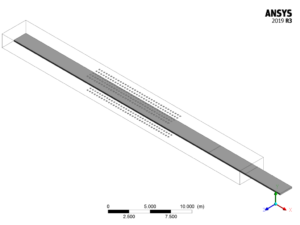
The geometry for analyzing this simulation consists of a chamber in which water is injected and molten steel enters inside this canal to lose its temperature and solidification. Geometry is designed in ANSYS design modeler® and is meshed in ANSYS meshing®. The mesh type is unstructured and the total element number is 560362.
The following figure shows the geometry of the modeled solidifying chamber

The following figure shows the mesh of the modeled solidifying chamber
Solidifying CFD simulation settings
The assumptions considered in this project are:
- Simulation is using a pressure-based solver.
- The present simulation is transient. 500 time steps with a step size of 1 second are exploited for this simulation.
- The effect of gravity has been taken into account and is equal to -9.81m/s2 in the Y direction.
The applied settings are recapitulated in the following table.
| (solidifying) | Models | |
| Viscous model | k-epsilon | |
| k-epsilon model | Standard | |
| near-wall treatment | standard wall function | |
| Multiphase | VOF | |
| Phase 1 | Air | |
| Phase 2 | Water | |
| Phase 3 | Steel | |
| Energy | On | |
| (solidifying) | Boundary conditions | |
| Inlets | Mass-flow inlet | |
| Water inlet(both inlets) | Mass flow rate | 16 Kg/s |
| Outlets | Pressure outlet | |
| Walls | ||
| wall motion | stationary wall | |
| Heat flux | 0 W/m2 | |
| (solidifying) | Solution Methods | |
| Pressure-velocity coupling | Coupled | |
| Spatial discretization | pressure | PRESTO! |
| Volume fraction | Compressive | |
| momentum | first-order upwind | |
| turbulent kinetic energy | first-order upwind | |
| turbulent dissipation rate | first-order upwind | |
| Energy | first-order upwind | |
| (solidifying) | Initialization | |
| Initialization method | Standard | |
| gauge pressure | 0 Pa | |
| velocity (x,y,z) | 0 m/s-1 | |
| Turbulent kinetic energy | 1 m2/s2 | |
| Turbulent dissipation rate | 1 m2/s3 | |
| temperature | 300 K | |
Results
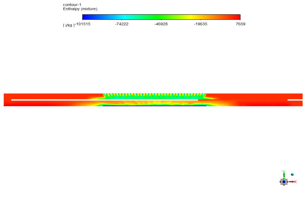
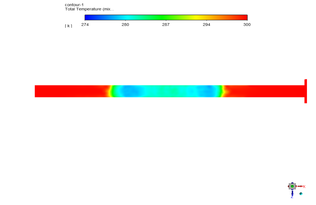
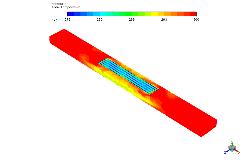
At the end of the solution we obtain contours of temperature, velocity, pressure, and enthalpy.





Estelle Connelly PhD –
Does simulation predict the final microstructure of the solidified steel?
MR CFD Support –
Yes, the simulation provides detailed information about the temperature distribution and solidification rate, predicting the final microstructure requires additional models that can be incorporated upon request.
Prof. Luna Denesik –
I want to ask if the simulation can be adjusted to account for different cooling rates
MR CFD Support –
Yes, the simulation can be adjusted to account for different cooling rates, which can significantly affect the solidification process and the final properties of the steel.
Deborah Stokes –
How does the simulation handle the shrinkage that occurs during solidification?
MR CFD Support –
The simulation includes a model that accurately captures the shrinkage that occurs during the solidification of the molten steel.
Dolly Bernhard –
Can this simulation be used to optimize the solidification process?
MR CFD Support –
Absolutely! The simulation provides detailed information that can be used to optimize the solidification process and improve the quality of the final product.