Splitter Erosion CFD Simulation Training using DPM by ANSYS Fluent
$100.00 $50.00 Student Discount
In this study, using the DPM (Discrete phase material) method, the effect of impurities in the working fluid on the splitter erosion was investigated.
Click on Add To Cart and obtain the Geometry file, Mesh file, and a Comprehensive ANSYS Fluent Training Video.To Order Your Project or benefit from a CFD consultation, contact our experts via email (info@mr-cfd.com), online support tab, or WhatsApp at +44 7443 197273.
There are some Free Products to check our service quality.
If you want the training video in another language instead of English, ask it via info@mr-cfd.com after you buy the product.
Description
Splitter Introduction
A splitter is a device for uniformly distributing incoming fluid flow by placing outlets of the same shape and size. Using Splitter, in addition to evenly dividing the initial flow rate, can absorb the impurities with a filter and increase the purity of the outlet gas. The impact of impurities such as sand and oxides of various metals can lead to erosion overtime on the body of various equipment. Therefore, studying the effect of erosion on transmission pipelines and fluid flow distribution will be of particular importance.
Problem Description
In this study, using the DPM (Discrete phase material) method, the effect of impurities in the working fluid on the body gas splitter was investigated. The impurity gas entered vertically at a speed of 5 meters per second and was directed out through 3 outlets. Using Ansys Fluent software, the impurity distribution, concentration, adsorption, and reflection in the installed filters were observed. Different erosion models in the software help correctly predict the erosion effect according to different working conditions.
Splitter Geometry & Mesh
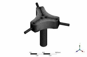
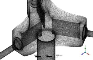
The designed geometry specifications include a gas splitter with three nozzles at the outlet. The inlet diameter of the mainstream is 1.6 cm, and the outlet nozzles’ diameter is 0.3 cm. In addition, 2.5 cm long fins are located inside the geometry as a filter (Figure below). (Design Modeler software)
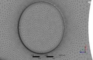
For grid generation, unstructured mesh with 2728426 elements in the ANSYS Meshing module was utilized. The curvature and proximity method focused on grid-sensitive areas like close to fins. Also, the boundary layer mesh next to the walls was used to satisfy the turbulence model Y+. The following figure shows the mesh generation for this problem.
Solver Setting
ANSYS Fluent software was used to solve the governing equations numerically. The problem is analyzed steady using the pressure-based method, and the gravitational effects were not considered. Also, for solving the above problem, RANS Includes discrete phase particles by integrating the force balance on the particles, which is written in a Lagrangian reference frame. This force balance equates the particle inertia with the forces acting on the particle.
Material Properties
Due to the high-speed internal flow in the computational domain, the natural gas density was assumed to be constant and thermodynamic characteristics such as viscosity and thermal conductivity of gas and impurity density were set.
Boundary Conditions and Solution CFD Methods
Also, The table below shows the characteristics and values of boundary conditions, along with the models and hypotheses.
| Material Properties (Erosion) | |||
| Natural gas | |||
| Amount | Fluid properties | ||
| 0.65 | Density (kg/m3) | ||
| 0.00013 | Viscosity (kg/m.s) | ||
| Inert-particle (impurities) | |||
| Amount | Fluid properties | ||
| 1600 | Density (kg/m3) | ||
| Discrete phase model (DPM) | |||
| Interaction with continuous phase (Erosion) | 10 continues phase iteration per DPM | ||
| Max step tracking | 50000 | ||
| Step length factor | 5 | ||
| Physical model | Erosion/Accretion
Generic model Finnie Oka |
||
| Accuracy Control | 1e-5 | ||
| Max.Refinement | 20 | ||
| Tracking Scheme Selection: | Trapezoidal | ||
| Injection type: | Surface velocity inlet | ||
| Diameter Distribution: | uniform | ||
| Diameter: | 0.15mm | ||
| Total flow rate: | 0.04627kg/s | ||
| Drag law: | Spherical | ||
| Turbulent Dispersion: | Stochastic Tracking
Discrete Random Walk Model Random Eddy Lifetime Number of Tries 10 Time Scale Constant 0.3 |
||
| The number of particles tracked: | 24900 | ||
| The number of particles trapped: | 8202 | ||
| The number of particles that escaped: | 16695 | ||
| Initialize: | standard | ||
| Boundary Condition (Erosion) | |||
| Type | Amount (units) | ||
| Velocity inlet | 5 m/s | ||
| pressure outlet (gauge pressure) | 0 pa | ||
| domain wall | |||
| Fin wall | trap | ||
| External domain wall | escape | ||
| Cell zone condition | |||
| Fluid | Natural gas | ||
| Turbulence models (Erosion) | |||
| K- | viscous model | ||
| Realizable | K- model | ||
| Enhanced-wall treatment | Wall function | ||
| Solution methods (Erosion) | |||
| SIMPLE | pressure velocity coupling | ||
| Standard | pressure | spatial discretization | |
| Second-order upwind | momentum | ||
| First-order upwind | turbulent kinetic energy | ||
| First-order upwind | turbulent dissipation rate | ||
Splitter Results
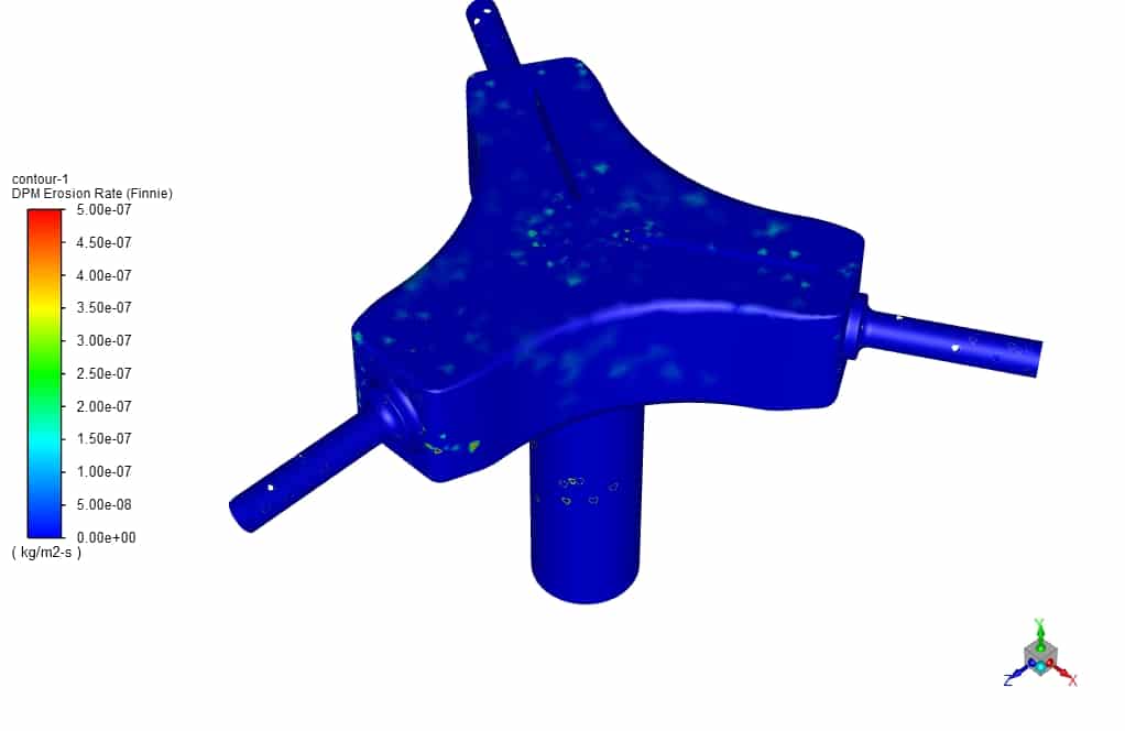
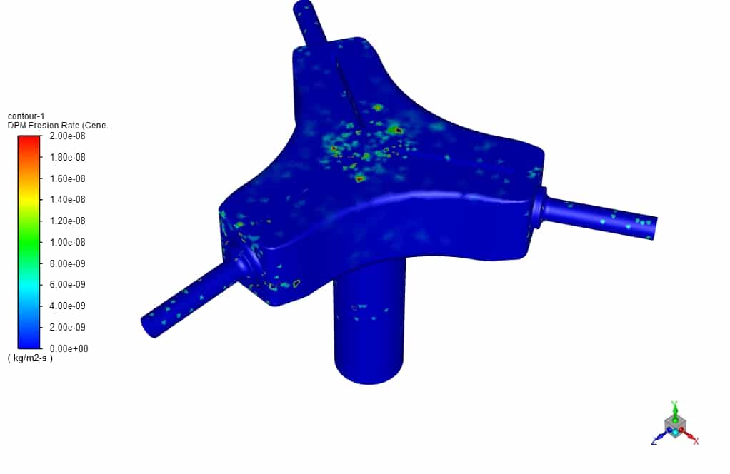
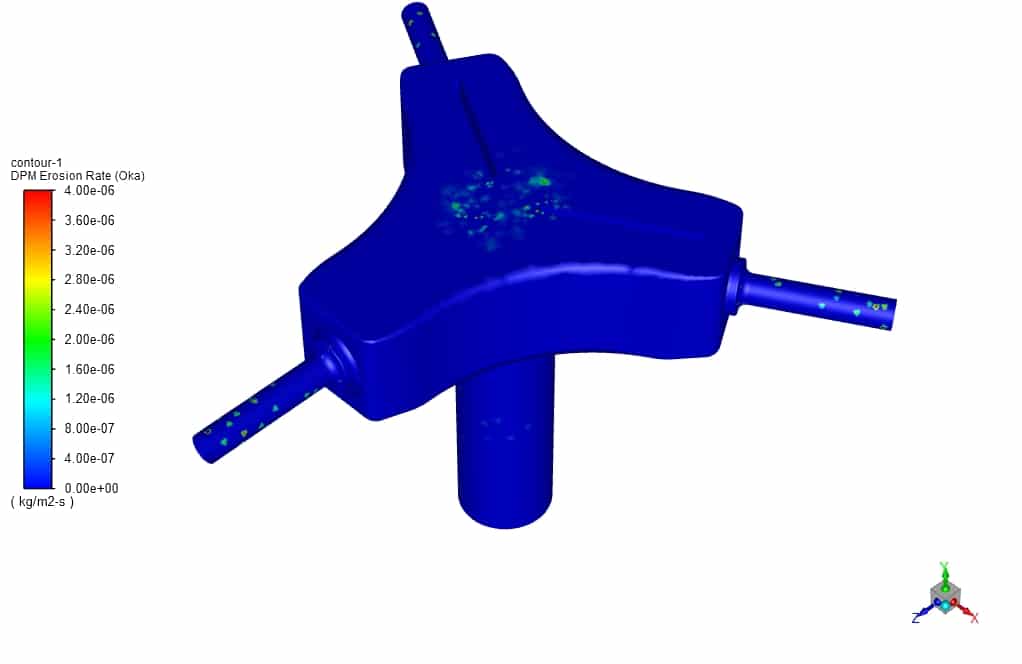
In this section, erosion models are first examined. The generic model can be used as an analytical equation for most cases because the material of impurities in this model is sand, which is present in most models. In model Finnie, which, like Oka and Mclaury models, uses an empirical correlation to predict erosion, it is mainly used for malleable materials. The Collision angle and velocity are effective. The model Oka considers the effect of wall hardness and may be more suitable for investigating the erosion of transmission pipes. Model Mclaury is used to study suspended solids in water and was unsuitable for the present case.
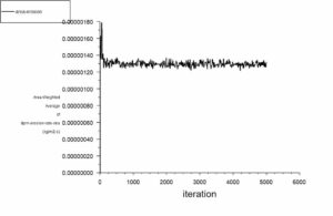
According to the above observations, by erosion contours of the splitter wall and examining the appropriate models, it was observed that in all models, the impact of particles on the upper wall due to high fluid velocity causes more erosion compared to other areas. The outlet nozzle walls are then subject to higher erosion. Oka Erosion diagrams have also been monitored during solution solving to better investigate the problem’s convergence.
Results
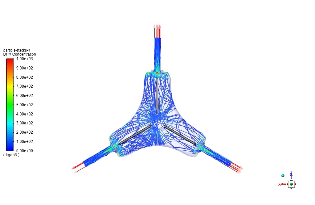
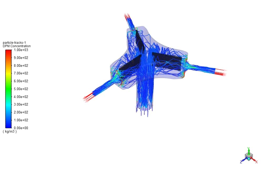
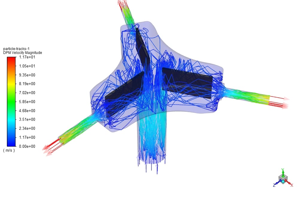
Examination of the contour of the impurity concentration shows that in the output part of the Splitter, due to the high velocity of the downstream flow and the reduction of cross-section, the exit of solid particles were challenging, and the accumulation of particles in that part causes the concentration of impurities to increase. However, due to the placement of filtered fins, can increase the adsorption of impurity particles, which can be seen in the table above by trap and escape particle track.


Brandy Armstrong –
This training product for splitter erosion using DPM sounds incredibly detailed. I’m curious though, did the study address how different particle sizes might affect erosion patterns and intensities?
MR CFD Support –
In the simulation, a uniform particle diameter of 0.15mm was considered for the discrete phase model (DPM), which assesses impurities interacting with the continuous phase leading to erosion. While the training product might not have directly addressed varying particle sizes, the specified uniform diameter provides insights into erosion patterns and intensities for that particular size. For a comprehensive understanding of erosion with respect to different particle sizes, additional simulations varying particle diameters would be required.
Barbara Emard –
The review lacks clarity regarding the specific erosion models’ suitability for different materials. Could you elaborate on that part?
MR CFD Support –
In the training, various erosion models like Finnie, Oka, and McLaury are discussed. Each model has its suitability for assessing erosion based on different material properties and flow conditions. The Finnie model is typically used for malleable materials where impact angle and velocity are crucial. The Oka model incorporates the hardness of the wall material, making it apt for exploring erosion in pipelines. McLaury’s model, while not applicable here, is commonly used for studying erosion due to suspended solids in water streams.
Yesenia Leannon –
Wonderful learning material! The detailed insight into splitter erosion and the usage of DPM in ANSYS Fluent is exceptional. I appreciate the versatility of the erosion models discussed, catering to various materials and conditions. The simulation seems comprehensive, with precise handling of complex flow dynamics, and the result analysis correlates beautifully with the theoretical expectations.
MR CFD Support –
Thank you for your kind words and appreciation of our training material! It’s wonderful to hear that the details on splitter erosion and the Discrete Phase Model execution could provide you with valuable insights. We strive to create content that captures the complexity of such simulations in accessible ways, and it’s rewarding to know we succeeded. Your feedback motivates us to continue delivering quality educational products. If you ever have more questions or need further assistance, do not hesitate to reach out to us.
Leonie Purdy –
Fantastic learning experience with the Splitter Erosion CFD Simulation Training! The detailed analysis of erosion models and the insights on particle tracking through DPM in ANSYS Fluent were particularly impressive. It’s clear that a lot of thought went into the design and execution of the simulation. The step-by-step approach made it easy to follow, and I can apply these concepts to my projects.
MR CFD Support –
Thank you for your kind words! We’re glad to hear that the Splitter Erosion CFD Simulation Training exceeded your expectations and provided you with valuable insights for your work. Our goal is always to deliver comprehensive and practical learning experiences. Your feedback is greatly appreciated, and we look forward to continuing to support your learning journey!
Arnoldo Blick –
This training seems pretty comprehensive. Could you explain if temperature effects are also considered in these erosion models, or are these calculations done under isothermal conditions?
MR CFD Support –
In this particular training, the simulations are run focusing on erosion patterns under steady-state conditions without specifying the inclusion of temperature effects. The evaluations are based on the DPM method, impurity interactions, and erosion rates without mentioning thermal dynamics, suggesting that temperature variations are not factored into the models, and the study is likely conducted under isothermal conditions.
Lenna Kreiger V –
I am truly impressed with the results provided by the Splitter Erosion CFD Simulation training. The comprehensive analysis of erosion and choice of models for different materials was very informative. The visualization of particle concentration and the complex motion within the splitter has greatly enhanced my understanding of splitter dynamics. Remarkable work on providing such detailed insights!
MR CFD Support –
Thank you for your positive feedback! We are glad to hear that the Splitter Erosion CFD Simulation training has enriched your knowledge about splitter dynamics and erosion analysis. It’s great that you found the visualizations and information comprehensive and insightful. If you have further queries or need more information, feel free to reach out to us.