Spoiler Effect on a Car Aerodynamics, ANSYS Fluent CFD Simulation Tutorial
$100.00 $50.00 Student Discount
- The present problem simulates a car in two modes with and without a spoiler using ANSYS Fluent.
- We design the 3-D model by the Design Modeler software.
- We mesh the model with ICEM software.
- We investigate drag and lift force in two modes: with spoiler and without spoiler.
To Order Your Project or benefit from a CFD consultation, contact our experts via email (info@mr-cfd.com), online support tab, or WhatsApp at +44 7443 197273.
There are some Free Products to check our service quality.
If you want the training video in another language instead of English, ask it via info@mr-cfd.com after you buy the product.
Description
Description
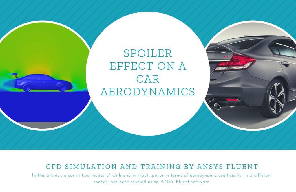
The present problem simulates a car in two modes with and without a spoiler in terms of aerodynamic coefficients, at 3 different speeds using ANSYS Fluent software. We perform this CFD project and investigate it by CFD analysis.
The present model is designed in three dimensions using Design Modeler software. The meshing of this project has been done with ICEM software.
Spoiler Methodology
In this project, the car’s geometry in two modes of with and without spoiler in terms of aerodynamic coefficients, in 3 different speeds with zero side angle, has been studied by ANSYS Fluent software.
The considered speeds are 22, 46, and 70 meters per second (m/s), and at the highest speed, the car’s stability in the case in which a spoiler has been added is examined.
Moreover, the SST k-omega model is enabled to solve the turbulent fluid equations due to its advantage in predicting flow patterns near and from the walls accurately.
Spoiler Conclusion
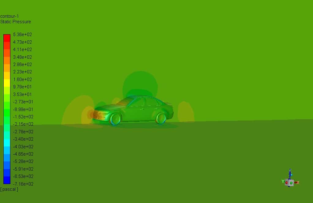
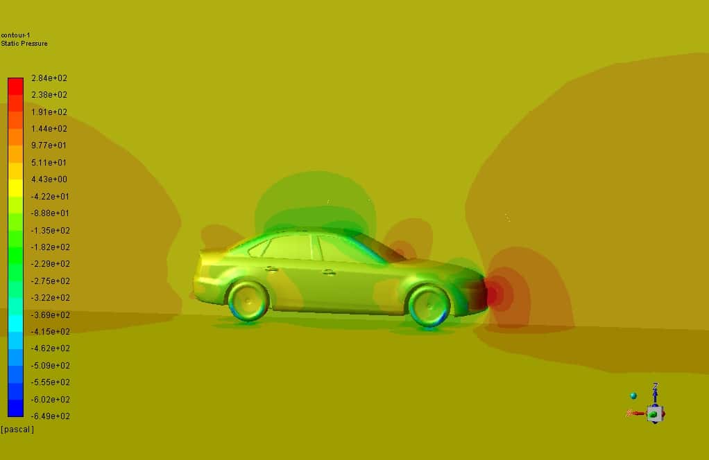
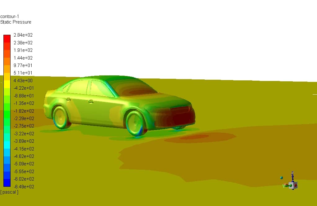
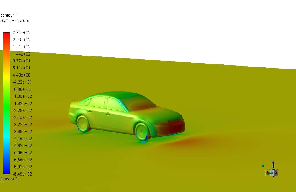
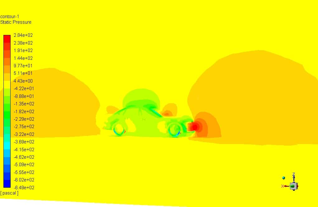
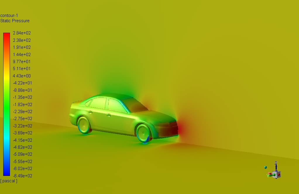
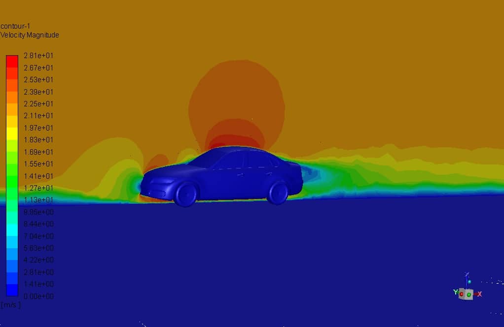
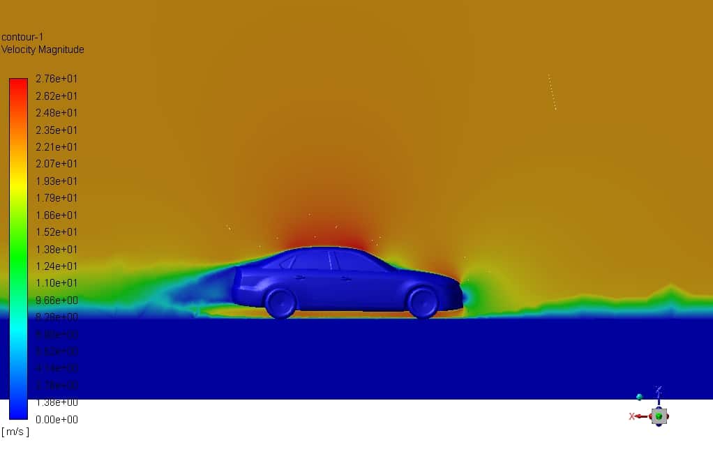
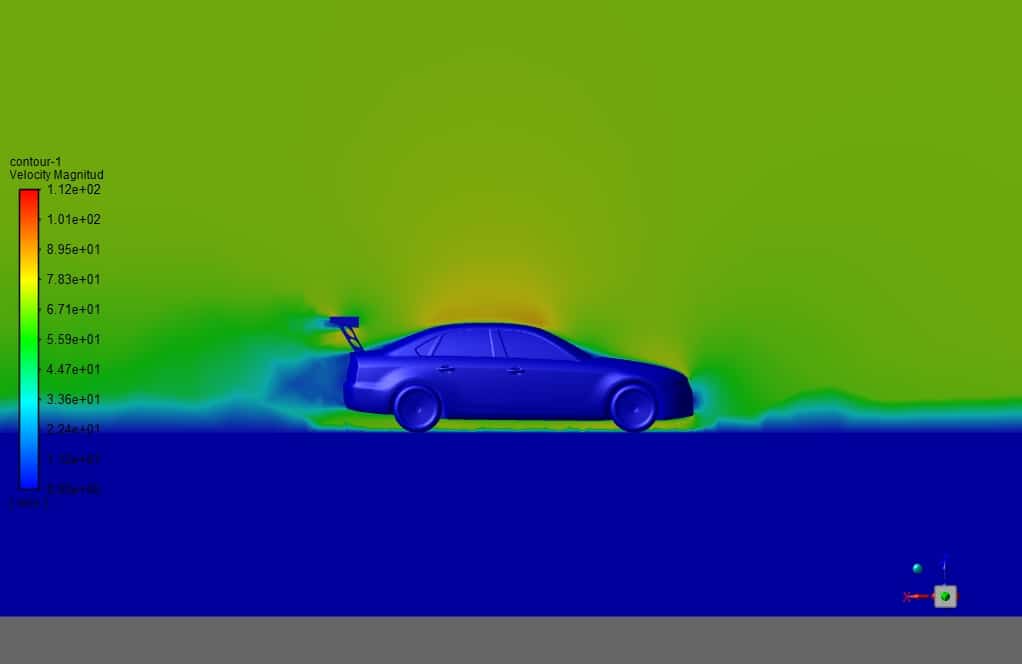
At the end of the solution process, two-dimensional contours related to pressure and velocity are obtained. As seen in the pressure contour, the pressure increases at the stagnation point on the car’s front section.
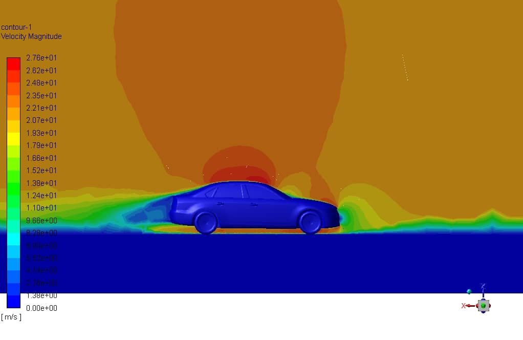
Also, the velocity contour clearly shows how the wake region is generated on the car’s rear section. Furthermore, based on the data calculated in Fluent, the following tables show the aerodynamic forces in two directions for two modes of with and without spoiler. Speed is in meters per second, and forces are Newtons.
| no spoiler | ||
| Velocity | fx | fz |
| 22 | 145 | -47 |
| 46 | 629 | -250 |
| 70 | 1467 | -527 |
| with spoiler | ||
| velocity | fx | fz |
| 22 | 184 | -243 |
| 46 | 796 | -1135 |
| 70 | 1847 | -2633 |
We can see from the diagrams and tables above that the drag force increases for the mode with the spoiler. As expected, the lift force increases in the direction the body sticks to the ground, so the car’s stability increases, which causes control at high speeds of the car to get better.




William –
Thank you for sharing this project.
Why did you use multiple inlets instead of one inlet and symmetry boundary conditions in the setup?
Cameron M. –
Can we do the meshing of this project in ANSYS meshing?
melika maysoori –
Yes, why not? 😉 Both of these software’s are for creating the computational grid and both have very high accuracy in creating an optimal mesh. Incidentally, using Ansys Mashing software to create Unstructured mesh is more convenient and easier than ICEM CFD. In fact, ICEM CFD software is mostly used to create the structured mesh. But considering that many of our projects have been done with Ansys Mashing software, in order to be able to explain the tips of ICEM CFD to those who are interested, we have generated mesh on some products with this software. In fact, working with either software depends on your skill and your goal of the simulation. 🙂