Steam Ejector in Refrigeration Cycle, Paper Validation
$280.00 $140.00 Student Discount
- The problem numerically simulates Steam Ejector in Refrigeration Cycle using ANSYS Fluent software.
- We design the 3-D model with the Design Modeler software.
- We Mesh the model with ANSYS Meshing software.
- The mesh type is Structured, and the element number equals 51990.
- This project is simulated and validated with a reference article.
- We use the Density-based solver to define Compressible flow.
To Order Your Project or benefit from a CFD consultation, contact our experts via email (info@mr-cfd.com), online support tab, or WhatsApp at +44 7443 197273.
There are some Free Products to check our service quality.
If you want the training video in another language instead of English, ask it via info@mr-cfd.com after you buy the product.
Description
Steam Ejector in Refrigeration Cycle CFD Simulation, Paper Numerical Validation, ANSYS Fluent
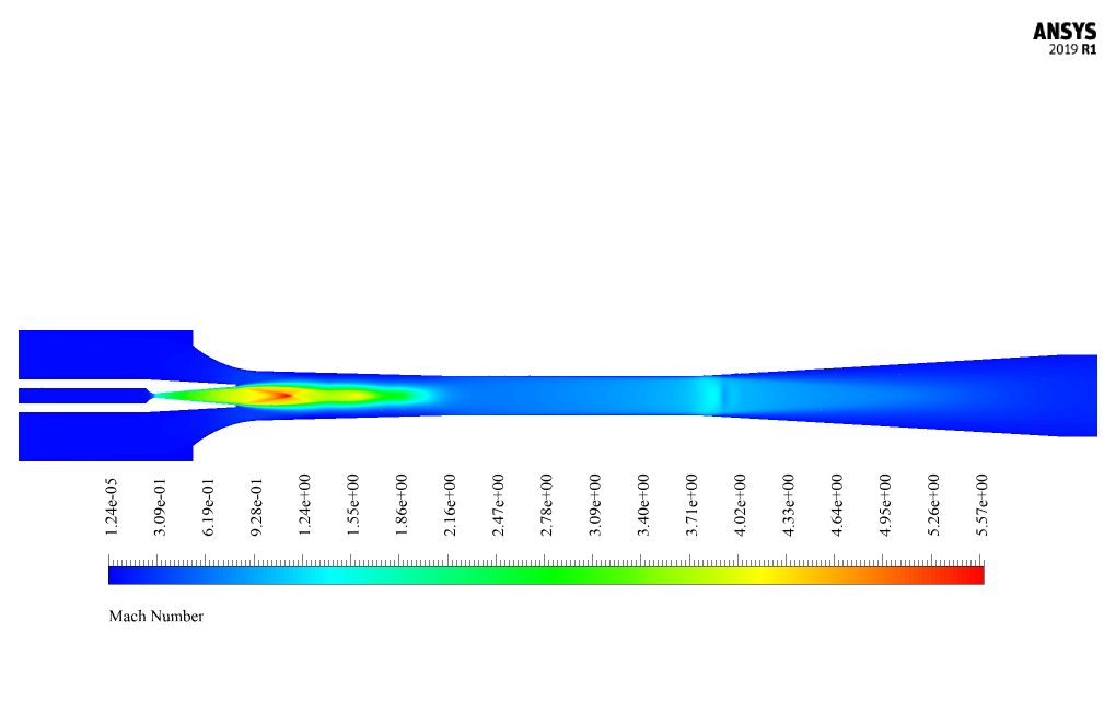
The present problem simulates the water vapor flow inside a steam ejector by ANSYS Fluent software.
This numerical simulation is based on the reference paper “CFD simulation on the effect of primary nozzle geometries for a steam ejector in refrigeration cycle” and the results of the present numerical simulation are compared and validated with the results in the reference article.
An ejector is a mechanical device that uses an actuator fluid to suck a secondary fluid (gas, liquid, or solid particles). Finally, the actuator fluid and the suction one are mixed together and exit the ejector. Ejectors have two main functions, including vacuuming and suctioning gases and mixing fluids.
The ejector modeled in the present work has a convergent-divergent structure; inside it, a convergent-divergent nozzle is located.
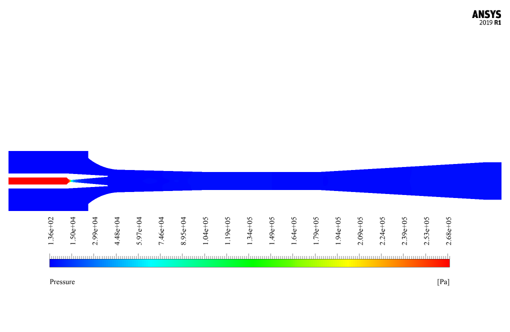
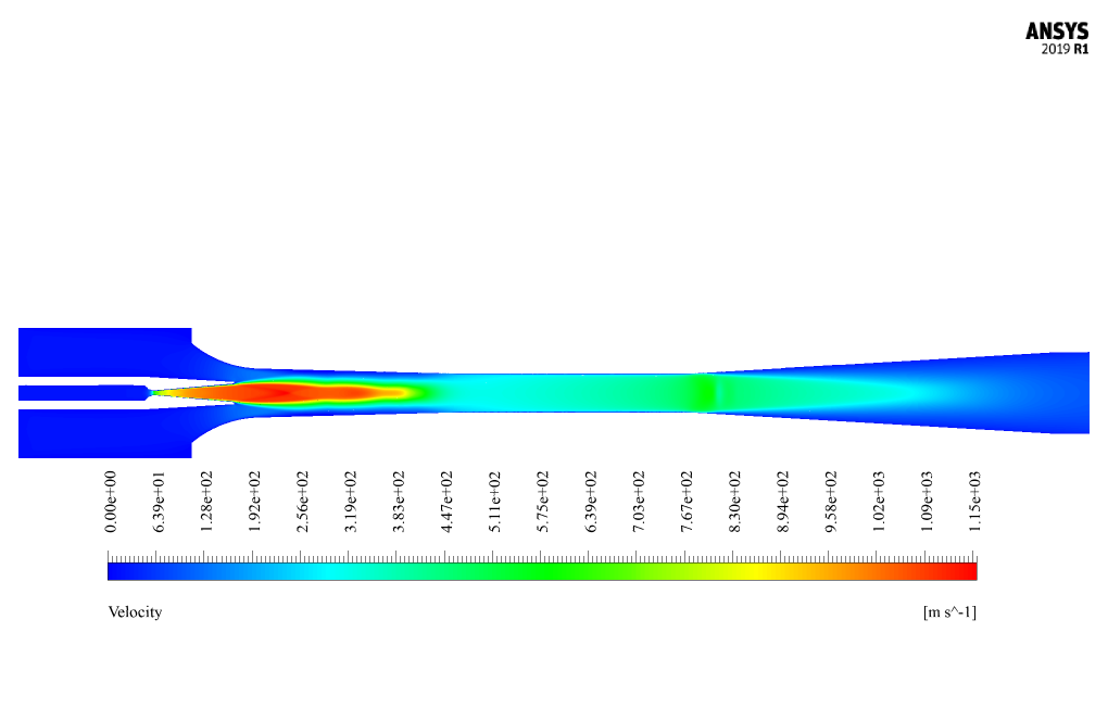
The operating mechanism of this ejector is such that the water vapor enters the ejector as the primary fluid, and by passing through the convergent part of the nozzle, which has a smaller cross-section, it accelerates. According to Bernoulli’s law, the pressure decreases.
On the other hand, this pressure drop causes a vacuum pressure inside the ejector and, as a result, causes the secondary fluid (suction) to suck into the ejector. The primary and secondary fluids are mixed in the diffuser section and compressed.
The present ejector is part of a refrigeration cycle; In this way, the primary inlet fluid comes from the boiler outlet, the secondary inlet fluid comes from the evaporator outlet, and the outlet goes to the condenser. The present model is designed in two dimensions using Design Modeler software.
Due to the symmetrical structure of the ejector nozzle and diffuser, only half of the ejector is designed. The geometry consists of two inlet sections for floes related to the primary and the secondary fluid, one outlet for the mixed output fluid, and an internal part as the nozzle for the primary fluid flow.
In terms of geometric scales, the model was designed based on Table 1 of the article (d2M4); So that the throat diameter of the nozzle related to the primary fluid is equal to 2 mm and the ratio of the ejector area (the ratio of the throat diameter of the ejector to the throat diameter of the primary fluid nozzle) is equal to 90.
The meshing has been done using ANSYS Meshing software, and the mesh type is Structured. The element number is 51990.
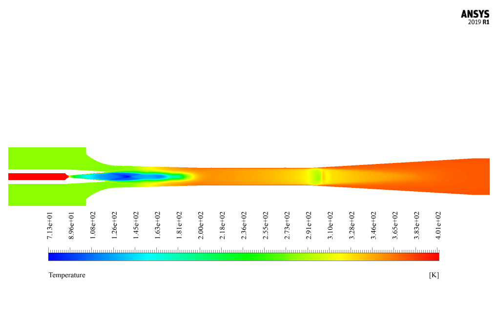
Water vapor from the boiler outlet in the cycle with a saturation temperature of 403.15 K and at a relative pressure corresponding to this temperature of 270,000 Pascal goes to the input of the primary fluid of the ejector.
On the other hand, water vapor is sucked into the ejector from the evaporator outlet with a saturation temperature of 280.65 K and a pressure corresponding to this temperature of 1000 Pascal.
Finally, the resulting mixed stream is discharged from the ejector outlet to the condenser with a saturation pressure of 3000 Pascal and a corresponding temperature of 297.23 K.
Steam Ejector Methodology
The simulation is Density-Based; Because in models such as the convergent-divergent nozzle, the fluid is compressible, and the flow Mach number is high.
Steam Ejector Conclusion
At the end of the solution process, the present numerical simulation results are compared and validated with the results in the article. For this purpose, the input ratio of the ejector (entrainment ratio) has been used.
This expression is equivalent to the ratio of the secondary fluid’s mass flow rate to the primary fluid’s mass flow rate. The mass flow rates of the primary and secondary fluids at the input points of the primary and secondary fluids were obtained using the Fluent software report, and the ratio was calculated.
This ratio has been compared and validated with the value in Table 3 of the reference article (the d2M4 mode in the table).
| Entrainment Ratio in reference paper | 0.2849 |
| Entrainment Ratio in present simulation | 0.286 |


Reviews
There are no reviews yet.