Submarine Design Optimization using RBF Method CFD Simulation, ANSYS Fluent Tutorial
$150.00 $75.00 Student Discount
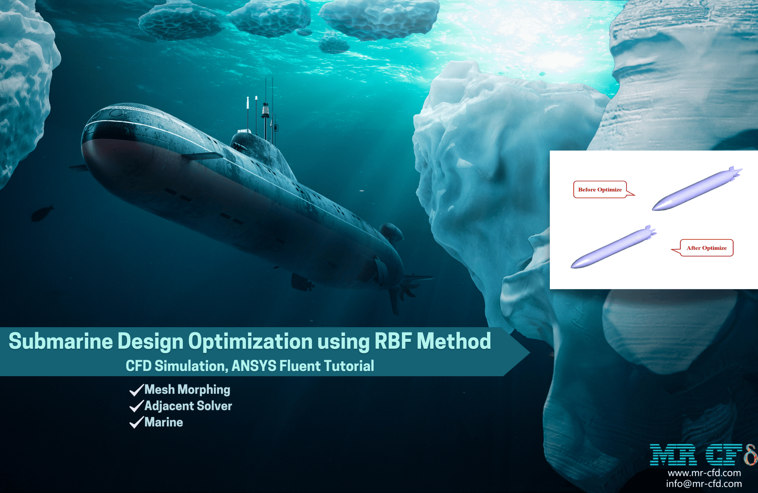
- The current CFD Analysis optimizes the geometry of a Submarine via ANSYS Fluent software.
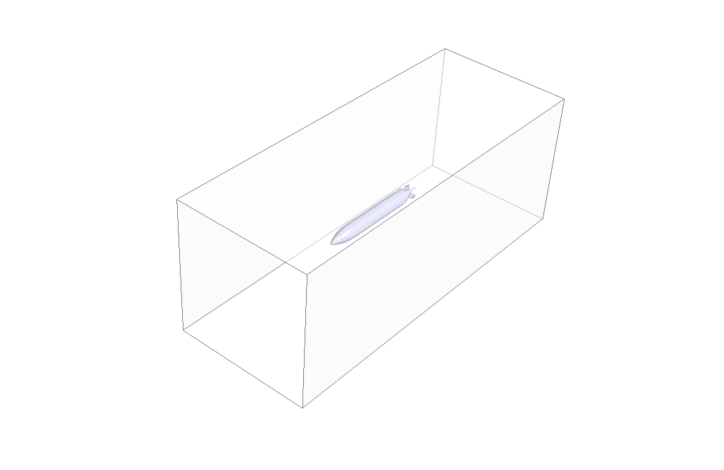
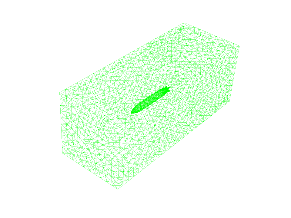
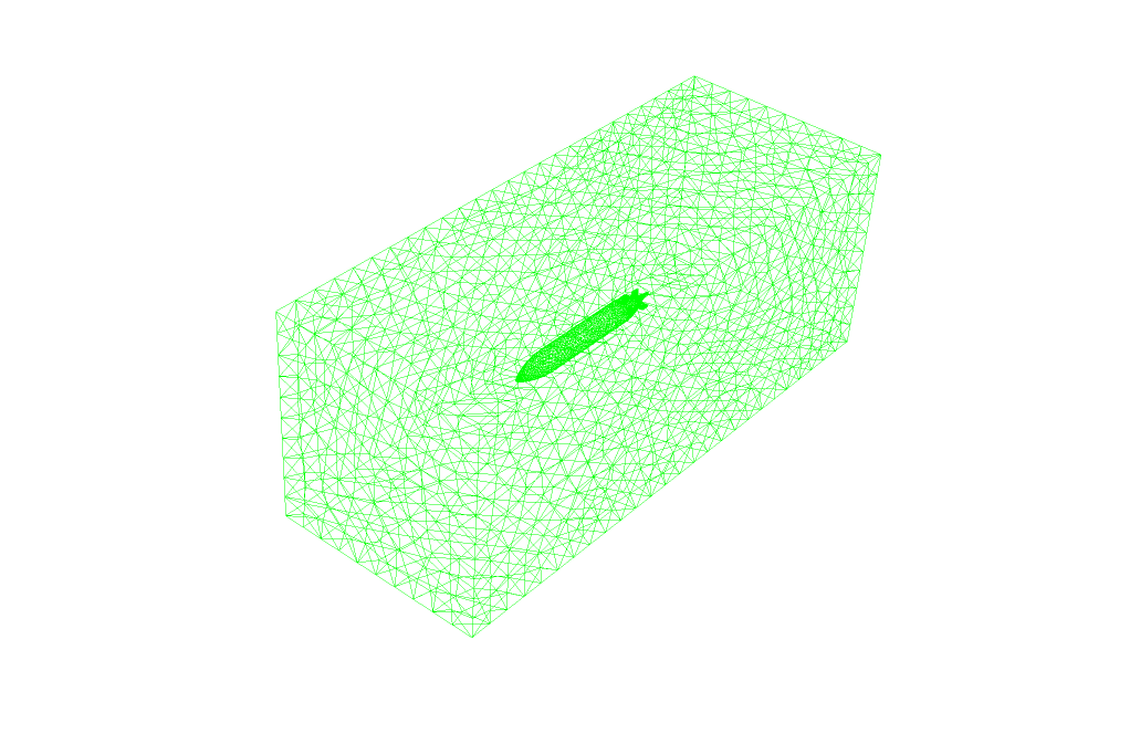
- We have designed the initial geometry using ANSYS Design modeler software and created the mesh on this geometry using ANSYS meshing software with 258,938 cells.
- RBF Morph (Adjoint Solver) is used for conducting the current problem.
To Order Your Project or benefit from a CFD consultation, contact our experts via email (info@mr-cfd.com), online support tab, or WhatsApp at +44 7443 197273.
There are some Free Products to check our service quality.
If you want the training video in another language instead of English, ask it via info@mr-cfd.com after you buy the product.
Description
Description
This simulation is about submarine design optimization using the adjoint solver (RBF Method) via ANSYS Fluent software.
When a structure moves with a certain speed in a continuous fluid, its body is subjected to forces from the fluid. For example, when a submarine moves through the water, forces from the water are applied to the submarine’s body. One of the important forces studied is the drag force.
This force is applied to the submarine’s body horizontally and against the direction of movement of the submarine. So this force creates resistance in the movement of the submarine.
Therefore, the drag force on the submarine has been investigated in this study. Drag force reduction must be considered in the design and construction of submarines. Reducing or increasing the drag force depends on the geometric structure and dimensions of the submarine body.
The CFD analysis of the drag force applied on the submarine to achieve a suitable geometry is done with the optimization process. There are many optimization methods for body design. ANSYS Fluent software uses an adjoint solver tool for geometric optimization. This tool has the ability to make changes in the dimensions of the target geometry by performing a solution process. These changes continue until an optimal geometry is obtained.
In this simulation, the optimization process based on the adjoint solver is used to reduce the drag force. The optimization process with the adjoint solver tool is done in three steps. First, the simulation has been done in normal mode with a basic geometry for a submarine with Ansys Fluent software.
Drag force is calculated in this mode. In the second step, the adjoint solution is used by defining a target parameter (drag force). The adjoint solution determines which areas of the submarine geometry are most sensitive to the amount of drag force.
With this work, it is possible to identify which geometrical changes in which areas of the geometry lead to geometrical optimization. In the third step, the optimization process has been done based on a defined percentage to reduce the target parameter (drag force).
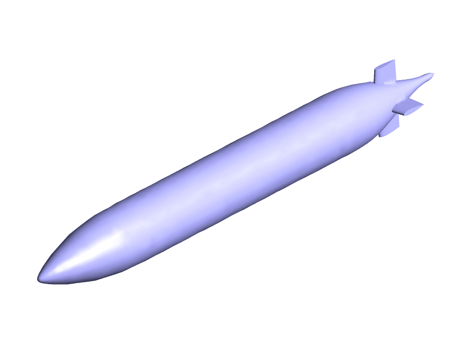
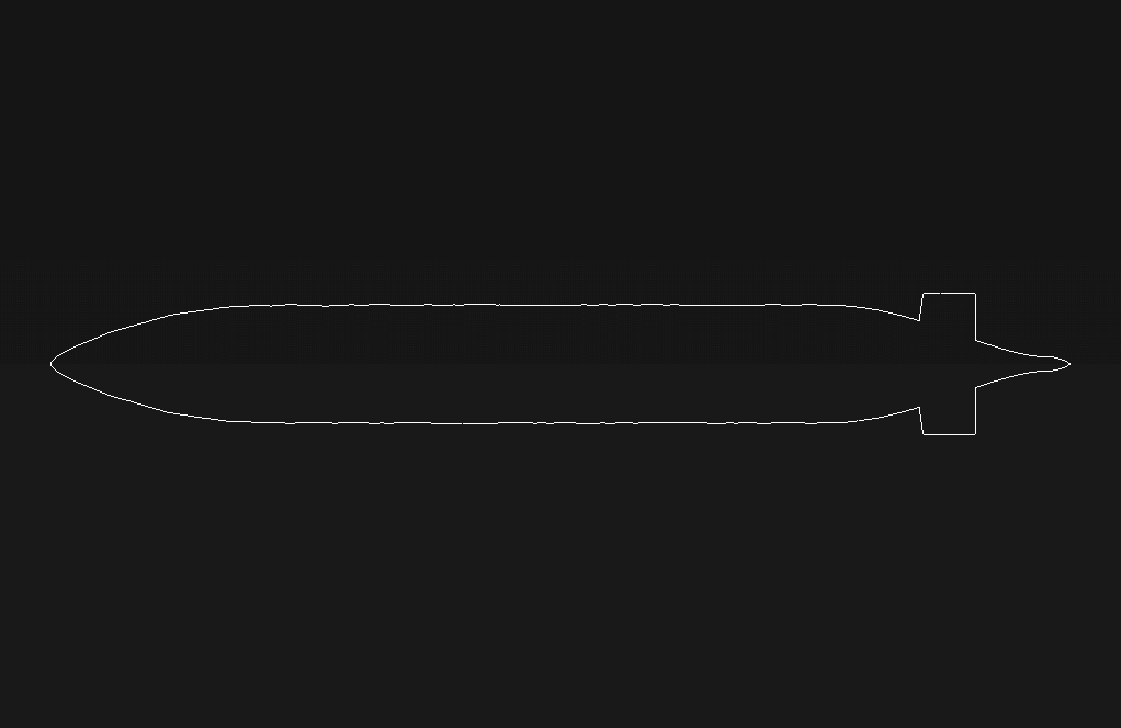
The geometry of the present project is modeled in three dimensions with Design Modeler software. The model is related to a simple submarine submerged in the water.
Then the model meshed with Ansys Machining software. The model’s grid is unstructured, and 258,938 cells have been created.
Methodology: Submarine Design Optimization using RBF Method
In this simulation, the configuration of a submarine is optimized based on the amount of drag force. First, a simple simulation was done for the water flow around the submarine to obtain the initial drag force. Now the goal of the problem is to minimize the drag force. The design tab is used for optimization.
First, drag force should be defined as the target quantity in the visible part. Then, the method section should determine discretization methods for the adjoint solver. Finally, the adjoint solution process is done. This solver can provide shape sensitivity value. This means determining which areas of the model are most effective for changing the drag force.
In the last step, the final optimization should be done. So it is referred to as the design tool, and the polynomial method is used in the morphing method section. Then, the drag force is selected as the target force in the objective section.
For defining the decrease in drag’s value, the decrease option is determined with a specific value in terms of percentage. In the region section, a dimensional range is selected from around the model so that geometric changes only occur in this space.
Finally, the optimization solution process is done in the gradient-based optimizer section.
Result
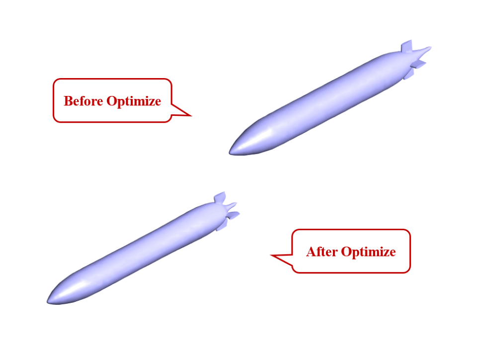
After the end of the simulation, the drag force was analyzed. In the initial modeling, the drag force was equal to 11.485855 N. After performing the optimization operation using the adjoint solver, the drag force was equal to 6.4377518 N. This means that the drag force is reduced by 44%. So it is concluded that the optimization of the model has been done correctly.
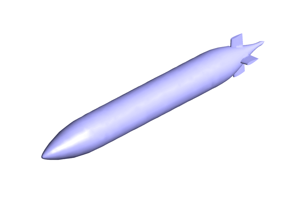
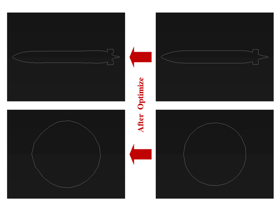
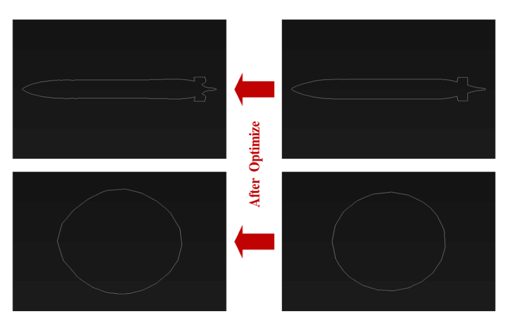
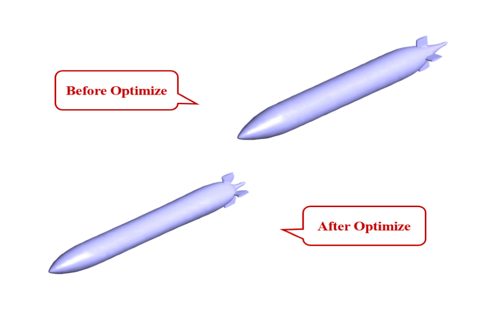
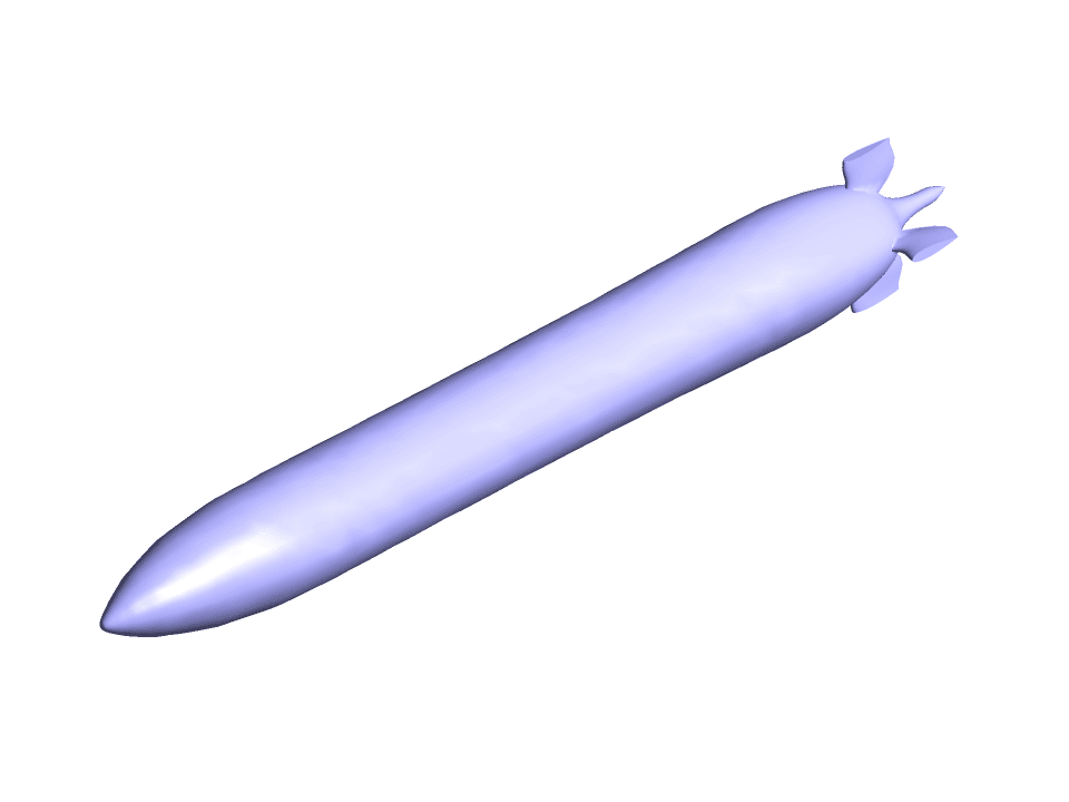
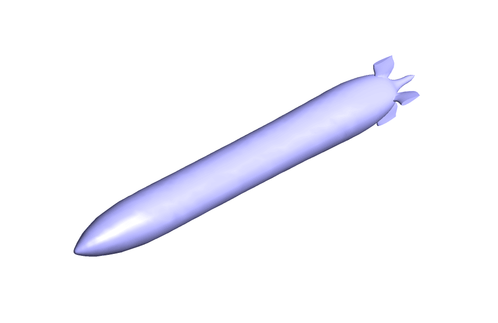
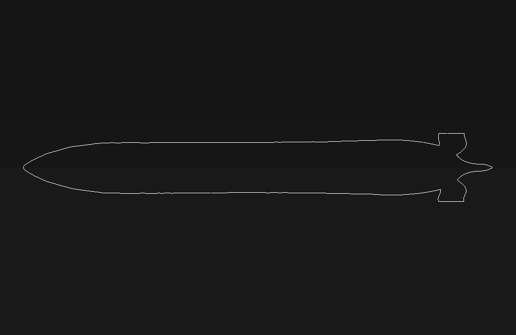
This reduction in drag force was made possible by making geometrical changes in the model. So, changes were made in the dimensions of the model. The iso-clip tool has been used to check the range of changes before and after optimization.
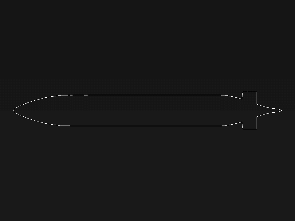
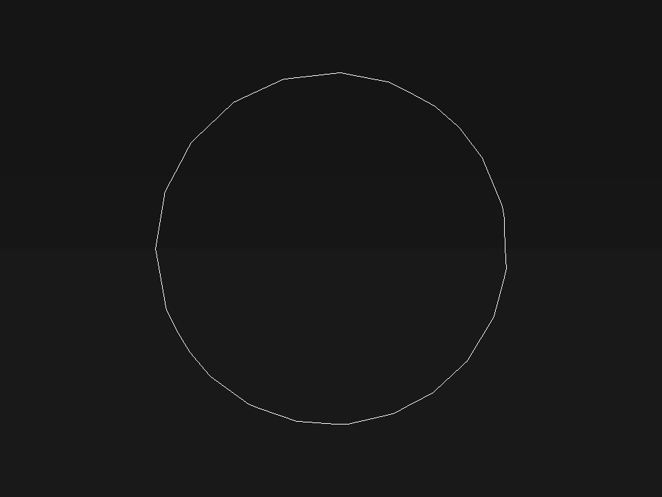
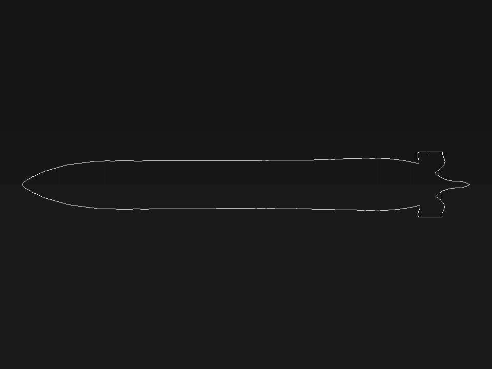
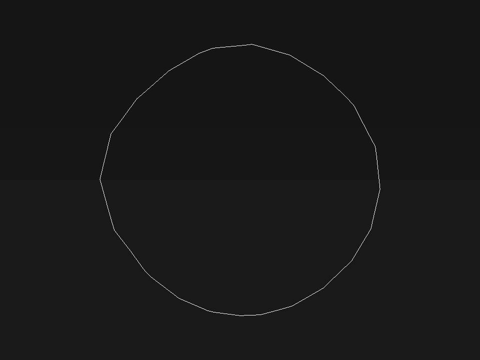
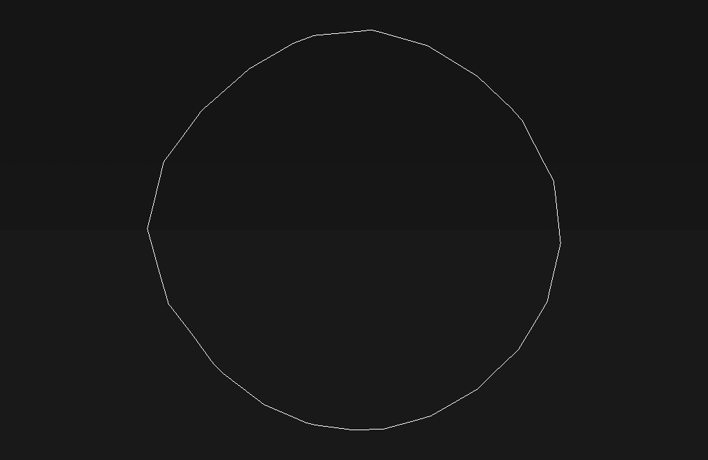
Dimensional changes have been investigated in the cross-section and side section. In the cross-section, the dimensions have changed from 0.5066175*0.5063399 to 0.4386431*0.453043. In the side section, the dimensions have changed from 4.353052*0.6 to 4.09195906*0.5952543.
Since the drag force is related to the cross-sectional area, reducing the cross-sectional area leads to a decrease in the drag force. The results of this simulation also confirm this issue. In addition, the drag force equals the sum of the pressure drag force and the frictional drag force.
Pressure drag is caused by the difference in water pressure between the two sides of the submarine. So, the smaller the cross-section of the submarine, the smaller this pressure difference. Frictional drag also depends on the side surface of the submarine. So, the lower the side surface of the submarine, the lower the drag force.


Reviews
There are no reviews yet.