Submarine Robot motion in a Water Channel, Dynamic Mesh, ANSYS Fluent
$140.00 $70.00 Student Discount
The present problem simulates the movement of a submarine robot inside a canal containing water flow using ANSYS Fluent software.
Click on Add To Cart and obtain the Geometry file, Mesh file, and a Comprehensive ANSYS Fluent Training Video.To Order Your Project or benefit from a CFD consultation, contact our experts via email (info@mr-cfd.com), online support tab, or WhatsApp at +44 7443 197273.
There are some Free Products to check our service quality.
If you want the training video in another language instead of English, ask it via info@mr-cfd.com after you buy the product.
Description
Project Description
The present problem simulates the movement of a submarine robot inside a canal containing water flow using ANSYS Fluent software. The dynamic mesh method has been used to simulate the horizontal movement of this robot inside the channel. In this simulation, a two-dimensional channel is designed to flow at a speed of 1.5 m.s-1. Simultaneously, the robot inside the canal moves horizontally in the water flow path at a speed of 3 m.s-1. Due to the fact that this robot is moving within the computational domain and thus affects the grids around it, so we need a momentary and time-dependent change in meshing based on the type of displacement in the adjacent boundaries of grids.
Therefore, to define the instantaneous change of meshing, the Dynamic Mesh model has been used. In the determination of dynamic mesh methods, smoothing and remeshing methods have been used. According to the smoothing method, the number of nodes connections does not change and only adjusts the mesh of an area by moving or deforming the borders. The remeshing method, on the other hand, is used when the displacement of the borders is large relative to the size of the local cells to regenerate the destructive cells of the critical size limit.
(Project Description)
In the definition of areas under the dynamic mesh, the wall part of the robot is defined as a rigid body. This means that the robot’s body acts as a rigid and integrated body and can be moved rotationally. This rigid body behavior means that the body itself does not change and only the meshing of the surrounding areas changes over time. Since the robot only moves horizontally at a certain speed, a profile is used to define this type of movement. This profile indicates the speed of the robot in the horizontal direction at different times. Due to the dependence of the dynamic mesh method over time, the present simulation process is defined as unsteady; So that the simulation is done in 1.5 seconds with a time step equal to 0.01 seconds.
Submarine Robot Geometry & Mesh
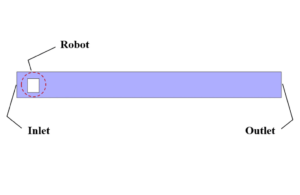
The present model is designed in two dimensions using Design Modeler software. The model is a two-dimensional channel in which a rectangular robot is placed. The channel has a length of 5 m and a width of 0.5 m. Also, the robot inside the channel has a length and width of 0.22 m and 0.27 m, respectively.
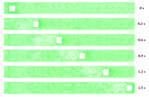
We carry out the model’s meshing using ANSYS Meshing software. The mesh type is unstructured. The element number is 2221. To better understand the mesh changes over time due to the use of the dynamic mesh method, we present several views for meshing at different times.
Submarine Robot CFD Simulation
We consider several assumptions to simulate the present model:
- We perform a pressure-based solver.
- The simulation is unsteady.
- We ignore the gravity effect.
The following table represents a summary of the defining steps of the problem and its solution:
| Models | ||
| Viscous | k-epsilon | |
| k-epsilon model | standard | |
| near wall treatment | standard wall function | |
| Dynamic Mesh | On | |
| mesh methods | smoothing & remeshing | |
| Boundary conditions | ||
| Inlet | Velocity Inlet | |
| velocity magnitude | 1.5 m.s-1 | |
| Outlet | Pressure Outlet | |
| gauge pressure | 0 pascal | |
| Walls | Wall | |
| wall motion | stationary wall | |
| Methods | ||
| Pressure-Velocity Coupling | SIMPLE | |
| pressure | second order | |
| momentum | second order upwind | |
| turbulent kinetic energy | first order upwind | |
| turbulent dissipation rate | first order upwind | |
| Initialization | ||
| Initialization methods | Standard | |
| gauge pressure | 0 pascal | |
| velocity (x,y) | 0 m.s-1 | |
Results
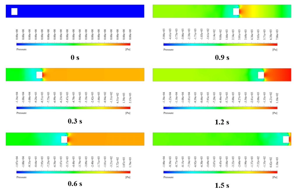
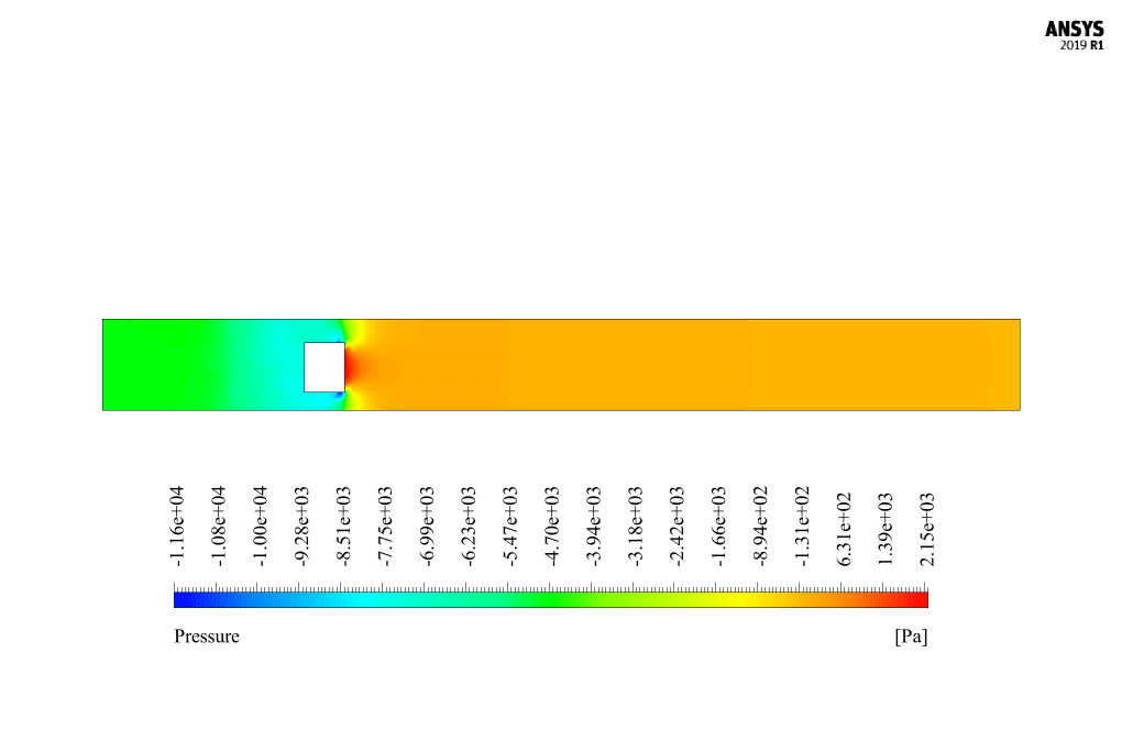
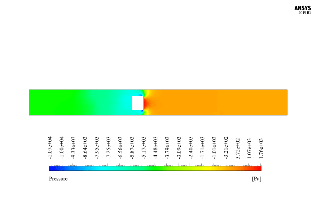
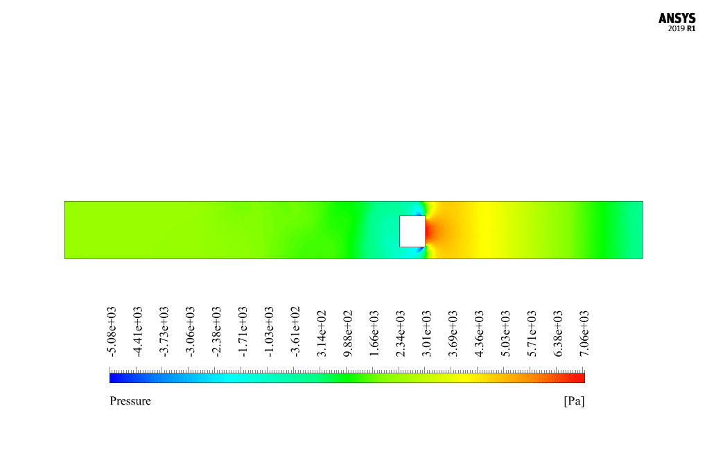
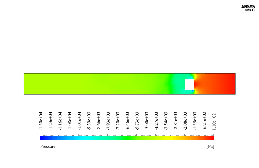
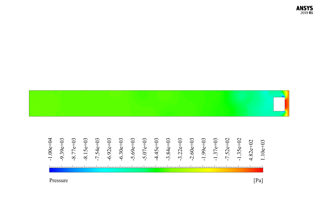
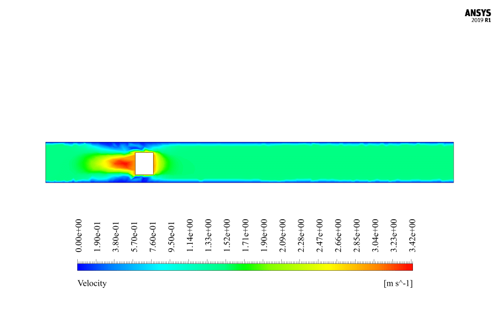
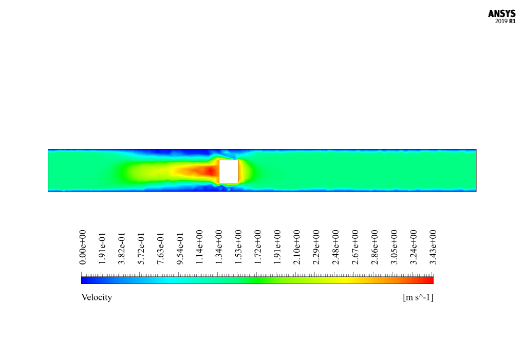
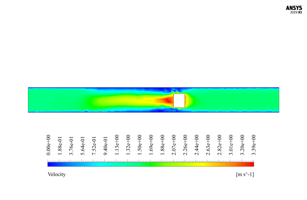
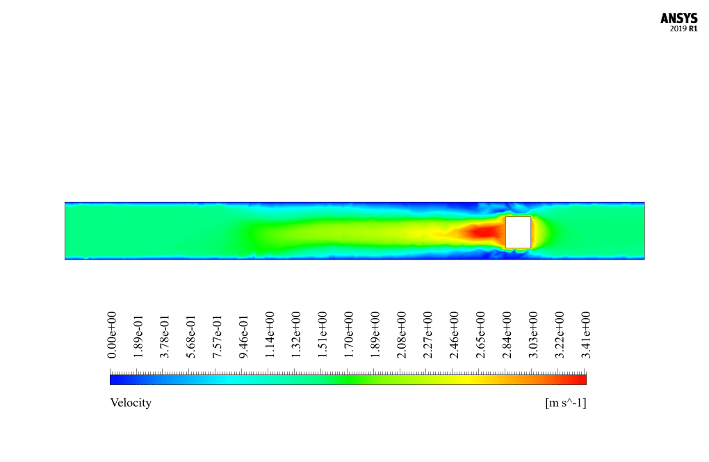
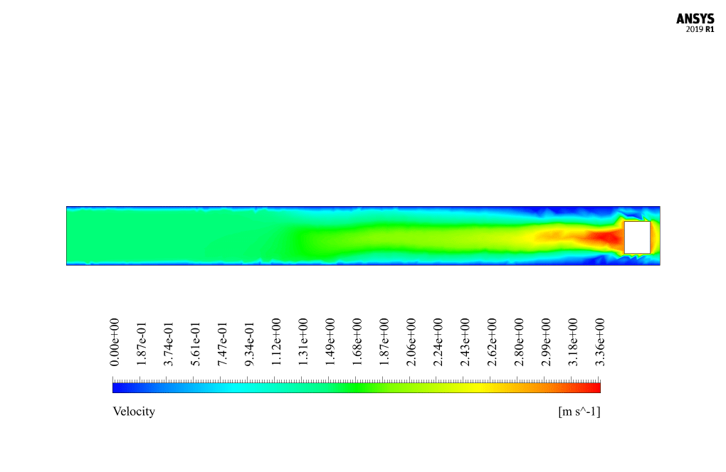
At the end of the solution process, we obtain two-dimensional contours related to velocity and pressure. Because the simulation is transient, we obtain contours at different times to compare the results over time. The contours show well that the robot in the channel has a horizontal movement and, over time, moves inside the channel containing the water flow. Also, due to the presence of the submarine robot body as a barrier in the flow of water inside the canal, a high-pressure area is created behind the submarine robot, and a high-speed area is created in front of it.


Miss Ollie Towne –
The simulation of the submarine robot was fascinating! The details very clear on how the dynamic mesh handled the movement of the robot within the fluid domain.
MR CFD Support –
Thank you for your positive feedback! We’re thrilled to hear you found the details on the dynamic mesh handling so clear and helpful. If you have any further questions or wish to learn more about such simulations, please let us know. We’re here to help!
Werner Nicolas –
Can you please explain why a pressure-based solver is used instead of a density-based solver in this submarine robot simulation?
MR CFD Support –
In this submarine robot simulation, a pressure-based solver is used because the flow is likely incompressible and subsonic, which is ideal for pressure-based algorithms. The robot movement and resulting flow patterns do not involve high-speed gas dynamics, shocks, or compressibility effects, making the pressure-based solver an efficient and accurate option for simulating the water channel flow characteristics. The solver can handle the fluid’s movement and pressure distribution while recalculating the dynamic mesh adjustments effectively.
Tillman Harvey –
The modeling and results presentation for the submarine robot in the water channel is impressive! I got a clear understanding of the mesh changes and the flow pattern around the moving robot.
MR CFD Support –
Thank you for your kind words! We’re delighted to hear that our submarine robot in the water channel simulation was informative and easy to understand. We strive to provide high-quality simulations and comprehensive results, and we deeply appreciate your feedback. If there’s anything more you’d like to learn about our simulations, please feel free to ask!
Rosalinda Rohan –
I found the use of dynamic mesh fascinating! How does the horizontal movement of the submarine robot affect the overall fluid behavior in the channel?
MR CFD Support –
The horizontal movement of the submarine robot inside the water channel creates a disturbance in the fluid’s flow patterns. As the robot moves, it introduces an obstruction to the natural flow, causing the water to redirect around the robot’s body. The presence of the robot leads to the formation of a high-pressure zone behind the robot and a high-velocity zone in front of it. Additionally, the robot’s movement may induce turbulence and vortex shedding in the water. Detailed simulations using dynamic mesh allow engineers to analyze these effects and understand the fluid-structure interactions involved.
General Thiel –
I am truly impressed by the capabilities of the dynamic mesh function demonstrated in this submarine robot simulation. The details about mesh changes over time and the resultant pressure and velocity impacts in different regions is fascinating. Well done on utilizing ANSYS Fluent so effectively.
MR CFD Support –
Thank you for your positive feedback! We’re delighted to know that the dynamic mesh functionality in the submarine robot simulation made an impression on you. Our goal is to harness the power of ANSYS Fluent to its full potential and provide insightful simulations. We appreciate your compliments on our work!
Abbey Erdman PhD –
I can see that a dynamic mesh model has been used which includes ‘smoothing and remeshing’. Could you provide more context on how this impacts the simulation results, especially considering the movement of the submarine robot?
MR CFD Support –
The use of a dynamic mesh model, with the combination of smoothing and remeshing techniques, allows the mesh—the collection of cells that the simulation domain is divided into—to adjust and conform to the changing geometry as the submarine robot moves through the water channel. This is crucial for accurately capturing the flow dynamics around the moving object. As the submarine robot progresses, the dynamic mesh enables the surrounding mesh to adapt dynamically. Smoothing adjusts the position of mesh nodes minimally to accommodate local geometry changes, preserving the mesh quality without creating or deleting elements, whereas remeshing regenerates elements when their size or shape becomes too distorted due to the large motions of the robot. This ensures that the fluid flow around the moving robot remains accurately resolved in the simulation throughout its movement, which affects the predicted pressure and velocity fields significantly.
Jacky Walter –
The explanation is very clear, but I am wondering, how is the gravitational effect considered in the simulation of the submarine robot, since it is usually a significant force in underwater environments?
MR CFD Support –
In the simulation of the submarine robot, the gravitational effect is actually ignored based on the provided project description. This is a commonly used simplification in certain CFD simulations to focus on the effects of flow dynamics and robotic movement. In this specific case, the key aspect is the interaction of the robot with the surrounding water flow, so gravity is not accounted for in the analysis.
Ms. Noelia Shanahan –
The project review was really informative. Kudos for the details on dynamic mesh handling for the submarine robot simulation! I’m curious, were there any specific constraints or challenges when defining the mesh quality criteria, considering the complexities involved in the robot’s motion?
MR CFD Support –
In the dynamic meshing process of submarine robot motion simulation, special considerations are required to maintain mesh quality given the complexity of the robot’s movement. To ensure adequate mesh quality throughout the simulation, careful preparations are taken to adjust local cell size and check for highly skewed cells. Proficient setup of smoothing and remeshing methods aims to handle large displacements, prevent mesh tangling, and preserve the integrity of the results by providing a capable mesh that adapts precisely to the evolving geometry of the moving robot.
Ignacio Wisoky –
I am thoroughly impressed by the level of detail in controlling the dynamic mesh, especially for simulating the robotic submarine’s motion. It seems like a complex problem handled very effectively using ANSYS Fluent. Were the results indicating any significant impact on the robot due to the high-pressure area formed behind it?
MR CFD Support –
Thank you for your kind words! The simulation indeed showed formation of a high-pressure area behind the submarine robot. This generally translates into a pressure drag on the object moving through the fluid. In the case of this particular simulation, the impact would have been meticulously calculated, allowing accurate predictions and assessments of the performance and efficiency of the submarine robot under the simulated conditions. These results can be incredibly valuable for making improvement decisions or for validating prototype designs of submarine robots.
Novella Aufderhar PhD –
This training was terrific! I gained in-depth insights about submarine robot simulations using dynamic mesh. The visualization of the pressure and velocity contours provided a clear understanding of the flow characteristics around the moving robot.
MR CFD Support –
Thank you for your positive feedback! We’re thrilled to hear that the submarine robot simulation training provided valuable knowledge and that the provided visualizations helped you comprehend the fluid dynamics. If you have more questions or need further assistance with similar simulations, feel free to reach out!
Gerardo Torphy –
I’ve completed the course and simulations for modeling the Submarine Robot motion in a Water Channel with Dynamic Mesh, but I am curious, are the high-pressure and high-speed areas consistent with real-life physics, and what factors could affect their accuracy in this simulation?
MR CFD Support –
In this simulation, the high-pressure area behind the robot and the high-speed area in front of it generally mirror what we’re likely to see in real-world hydrodynamics. These phenomenon arise due to the robot acting as a disturbance in the flow field, leading to flow separation and acceleration around its body. The accuracy of these results depends on factors such as the fidelity of the dynamic mesh, the turbulence model used (k-epsilon in your case), the spatial and temporal resolution of the simulation (mesh density and time step size), and the treatment of the boundary conditions. Each of these aspects can directly impact the simulation results, making thorough validation against experimental data or high-fidelity simulations crucial for confirming their realism.
Dr. Ralph Cronin –
This training material walked me through the steps beautifully. The dynamic mesh concept was tricky, but now it’s clear as day!
MR CFD Support –
Thank you for your wonderful feedback! We’re thrilled to hear that our training material helped clarify the dynamic mesh concept for you. Should you have any further questions or need additional learning resources, don’t hesitate to reach out.