Tank Charge (2-Phases) , CFD Simulation Ansys Fluent Training
$80.00 $40.00 Student Discount
In this project, a tank charge has been simulated and the results of this simulation have been investigated.
Click on Add To Cart and obtain the Geometry file, Mesh file, and a Comprehensive ANSYS Fluent Training Video.To Order Your Project or benefit from a CFD consultation, contact our experts via email (info@mr-cfd.com), online support tab, or WhatsApp at +44 7443 197273.
There are some Free Products to check our service quality.
If you want the training video in another language instead of English, ask it via info@mr-cfd.com after you buy the product.
Description
Tank Charge Project Description
The current project simulates the tank filling by Ansys Fluent software. In this project, we simulate Tank charge/filling (2-phase) between two reservoirs with fluid air and water and the Same height of tanks. The goal of many operations in the chemical industry is to separate the components of a solution or mixture from each other or to obtain a pure substance from a combination of two or more components. In this Tank Filling simulation, using the VOF (volume of fluid) method, the interaction of two phases, including water and the air, was investigated.
Geometry and mesh
The geometry of the solution consisted of two reservoirs that Each of them has dimensioned 1.25*2.5 m. The 2D geometry of this project has been produced with Ansys Design Modeler software.
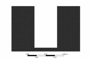
Mesh is created with Ansys meshing software, and the mesh type is structured. The number of cells is 32510.
Tank Charge CFD Simulation
We consider several assumptions to simulate the present model:
- Due to the incompressibility of the flow, the pressure-based solver method has been selected.
- The simulation is transient.
- The gravity effect is considered equal to -9.81 m.s-2on Y-axis
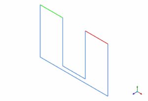
In the figure below, taken from Ansys CFD-post software, the red lines are related to temperatures. The blue lines are adiabatic, and the blue and orange lines are related to heat1 and wall. The type of walls, inlet vent, and outlet vent boundary conditions Also shown in blue, green, and red respectively a wall, inlet vent, and outlet vent.
The following tables represent a summary of the defining steps of the problem in this project and its solution.
|
Multiphase
|
Model
|
Volume of Fluid |
|
Number of Eulerian phases
|
2(air & water) |
|
|
Interface modeling
|
Sharp |
|
|
Formulation |
implicit |
|
|
Primary phase
|
air |
|
|
Secondary phase
|
Water |
|
|
Viscous
|
k-epsilon
|
Realizable |
|
Near wall treatment |
Standard wall functions |
|
|
Material Properties
|
||
|
Air
|
Density
|
1.225 |
|
viscosity |
1.7894e-05 |
|
|
water-liquid |
Density
|
998.2 |
|
viscosity
|
0.001003 |
|
|
Boundary conditions
|
||
|
Walls
|
|
wall
|
|
Wall motion |
Stationary wall |
|
|
Inlet-vent
|
Inlet-vent
|
|
|
gauge pressure |
0 pascal |
|
|
outlet-vent
|
outlet-vent
|
|
|
gauge pressure
|
0 pascal |
|
|
Pressure profile multipier |
1 |
|
|
Solution Methods
|
||
|
Pressure-velocity coupling
|
couple |
|
|
Spatial discretization
|
Pressure |
presto |
|
momentum |
second-order
|
|
|
Volume fraction
|
Compressive |
|
|
Turbulent kinetic energy
|
First-order upwind |
|
|
Turbulent dissipation rate
|
First-order upwind |
|
|
Initialization
|
||
|
Initialization method
|
Standard |
|
|
Patch
|
Phase |
water |
|
Variable |
Volume Fraction |
|
|
Zones to patch |
Surface-body |
|
|
value |
1 |
|
|
Run calculation
|
||
|
Time step size
|
0.001 |
|
|
Max iterations/time step
|
20 |
|
|
Number of time steps
|
10000 |
|
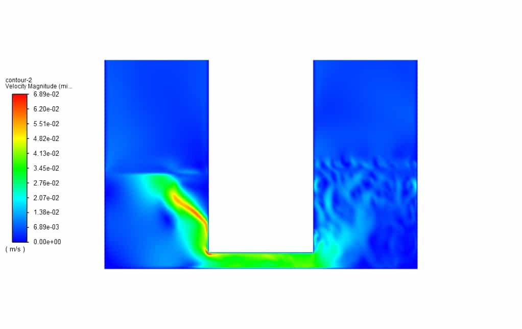
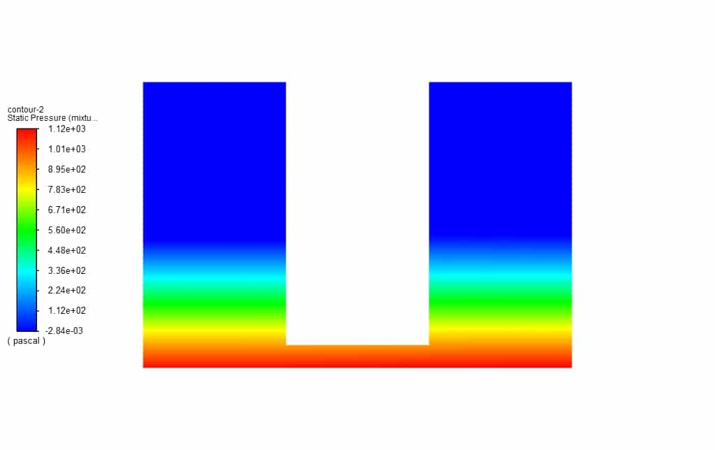
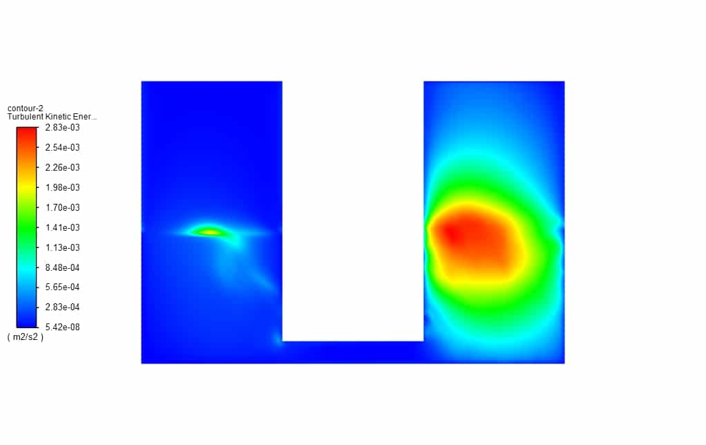
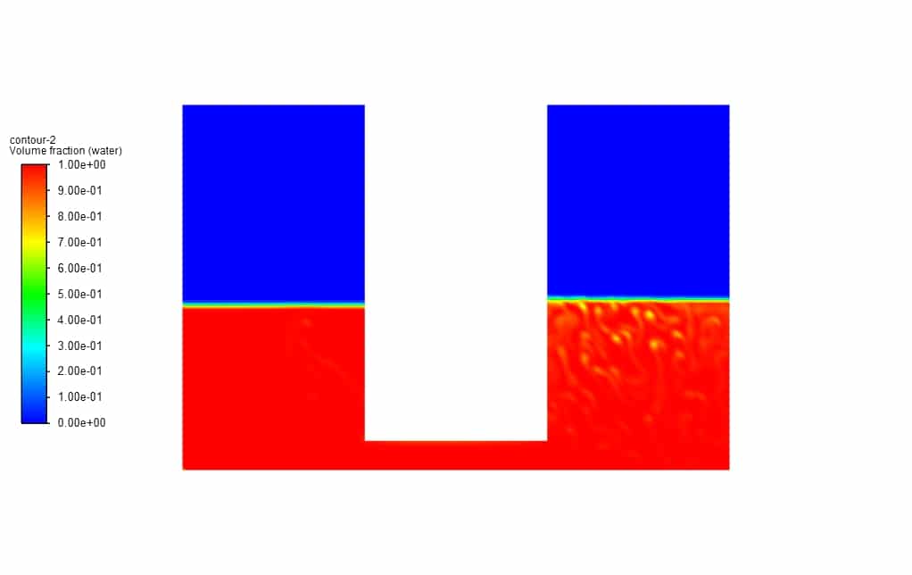
This simulation presents two-dimensional contours related to volume fraction, pressure, velocity, and turbulent kinetic energy. Also, as the attached animation shows, the air phase moves upwards by moving the water fluid towards the tank containing air. We observe After a few seconds and according to the law of hydrostatic pressure, the pressure is equal at the same heights.


Jeramy Labadie PhD –
The detailed review is highly insightful! However, I’m curious about the choice of mesh refinement. How would changing the mesh density affect the results of this particular simulation?
MR CFD Support –
If you increase the mesh density in the simulation, you would observe higher resolution data for fluid interactions, which can lead to more accurate prediction of turbulence and interphase phenomena. On the downside, this would also lead to higher computational costs and longer solve times. Conversely, coarser mesh might speed up the simulation but could compromise result accuracy, especially for subtle dynamics in the two-phase flow.
Gilbert Kovacek –
The simulation is fascinating! How does the tank change affect the phase distribution, especially given the hydrostatic pressure balance? Is it possible to see the movement of water and air during the filling of one tank from the other?
MR CFD Support –
Thank you for your keen interest! As reflected by the volume fraction contours and animations, hydrostatic pressure ensures pressure balance across corresponding heights in the tanks. As the water level rises in the filled tank, air gets displaced upwards. You can indeed visualize both water entry and air displacement by leveraging the contours of phase volume fractions, which depicts neat delineation between water and air phases, showcasing the fluid interactions vividly throughout the simulation process.
Ruthie Parker –
How does the simulation ensure that the heat transfer between the air and water during the tank charging process is accurate?
MR CFD Support –
The simulation considers the boundary conditions related to temperature for accuracy in heat transfer calculations. Red lines represent temperatures while blue and orange lines indicate the boundary conditions for heat1 and walls. By carefully applying these settings, the simulation provides precise modeling of thermo-fluid interactions.
Mr. Aurelio Grant PhD –
Where can I find the exact iteration settings that were used for this simulation?
MR CFD Support –
Indeed, the iteration settings are crucial for ensuring the simulation’s stability and accuracy. You can find the defined iteration settings like ‘Time step size’, ‘Max iterations/time step’, and ‘Number of time steps’ under the ‘Solution Methods’ and ‘Run calculation’ sections of your simulation setup documentation or within your case setup in ANSYS Fluent software. If you require more details or have specific questions about these settings, our support team will be happy to assist you.
Prof. Shirley Smitham –
The simulated charging process looks quite detailed. Have the results indicated a specific timeline for charge equilibrium, and is there any observed overshoot in the pressure due to momentum at the start of the charging process?
MR CFD Support –
Glad you find the charging process detailed! Our observations indicate that the charge equilibrium timeline and overshoot at the start are captured effectively in the simulation. We monitored the pressure and velocity fields to ensure realistic representation of both hydrostatic equilibrium and dynamic fluid behaviour, including any initial overshoot due to momentum.
Jadon Davis –
The visualization of the air phase motion in the animation is intriguing. Did the simulation account for any surface tension effects between air and water in the tanks?
MR CFD Support –
In our two-phase tank filling and charge simulation, we did consider the interaction of water and air phases. However, within the scope of the VOF model settings summarized in the project description, there is no direct mention of modeling surface tension effects between the air and water phases. The focus was primarily on volume fraction, pressure, and velocity profiles driven by gravity and hydrostatic pressure.