Tank Discharge CFD Simulation, Ansys Fluent Training
$80.00 $40.00 Student Discount
In this project, the Rectangular Tank’s water discharge has been simulated and the results have been investigated.
Click on Add To Cart and obtain the Geometry file, Mesh file, and a Comprehensive ANSYS Fluent Training Video.To Order Your Project or benefit from a CFD consultation, contact our experts via email (info@mr-cfd.com), online support tab, or WhatsApp at +44 7443 197273.
There are some Free Products to check our service quality.
If you want the training video in another language instead of English, ask it via info@mr-cfd.com after you buy the product.
Description
Tank Discharge Project Description
The current project simulates the water discharge of a rectangular tank under the influence of gravity by Ansys Fluent software. The VOF model has been used to simulate and solve the two-phase flow field equations. The computational domain consists of three tanks that are connected by pipes.
Geometry & Mesh
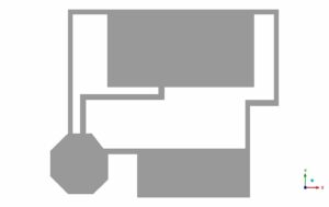
The 2-D geometry of the present model is generated using Design Modeler software. The primary tank is a 229.4* 157.7 mm rectangular, the second tank is an eight-sided polygon with a side length of 51.3 mm, and the third tank is also a 229.4* 100 mm rectangular.
. The meshing of this project has been done using Ansys Meshing software. The mesh type is unstructured, and the element number is equal to 15,310.
Tank Discharge CFD Simulation Settings
We consider several assumptions to simulate the present model:
- Due to the incompressibility of the flow, the pressure-based solver method has been selected.
- The simulation is transient.
- The gravity effect is considered equal to -9.81 m.s-1 on Y-axis
The Laminar viscous model has been used to solve the flow field equations, and the pressure-velocity coupling scheme is SIMPLE. The second-order upwind discretization method has been used for momentum and PRESTO! For the pressure discretization.
The following tables represent a summary of the defining steps of the problem in this project and its solution:
| Models | ||
| Multiphase | ||
| Homogeneous model | Volume of fluid | |
| Number of Eulerian phases | 2(air& water) | |
| Interface modeling | Sharp
Interfacial Anti-Diffusion |
|
| Formulation | Implicit | |
| Body force formulation | Implicit body force | |
| Viscous | Laminar | |
| Material Properties | |
| Air | |
| Density | 1.225 |
| viscosity | 1.7894e-05 |
| water-liquid | |
| Density | 998.2 |
| viscosity | 0.001003 |
| Methods | ||
| Pressure-Velocity Coupling | SIMPLE | |
| Pressure | PRESTO! | |
| Momentum | Second-order upwind | |
| Volume fraction | Compressive | |
| Cell registers | ||
| Input coordinates | ||
| X Min [m] | 0.08 | |
| X Max[m] | 0.379 | |
| Y Min [m] | 0.2264246 | |
| Y Max [m] | 0.33 | |
| Initialization | ||
| Initialization methods | Standard | |
| Patch | Phase | Phase2 |
| Variable | Volume Fraction | |
| Registers to patch | Region_0 | |
| Value | 1 | |
| Run calculation | ||
| Time advancement | Type | adaptive |
| Parameters | ||
| Initial time step size | 1e-05 | |
| Settings | Minimum time step size | 1e-05 |
| Maximum time step size | 0.001 | |
| Time step size | 10000 | |
Tank Discharge Results
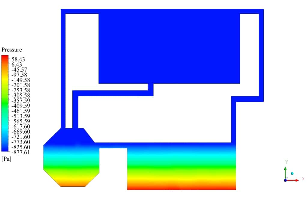
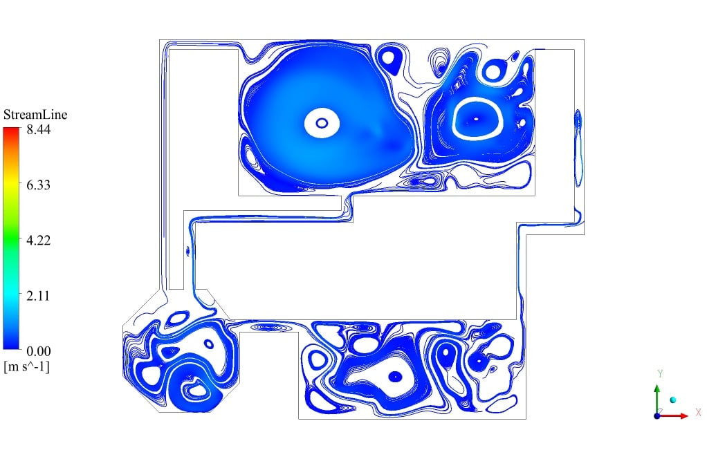
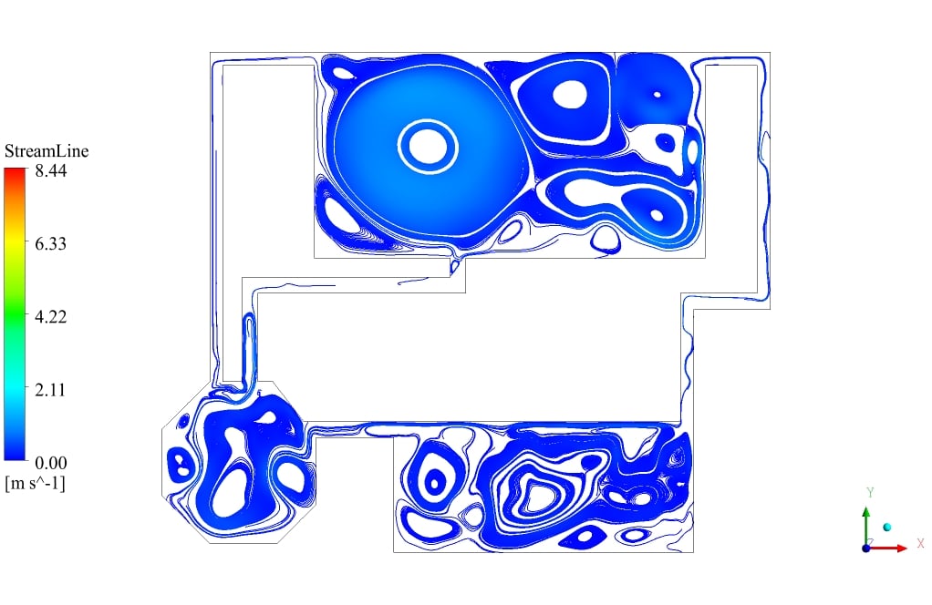
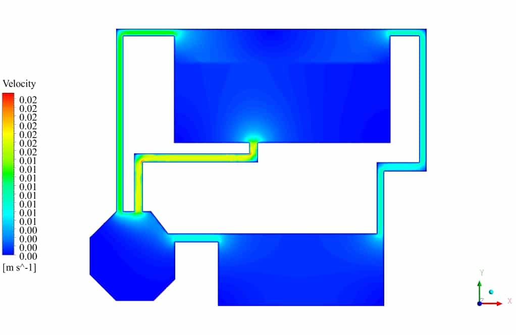
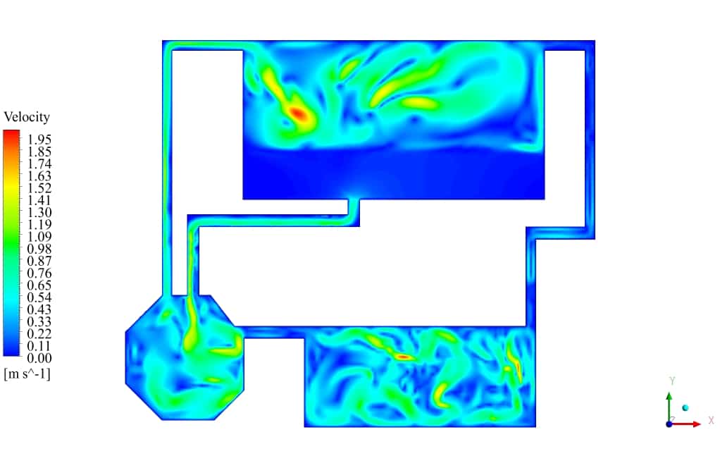
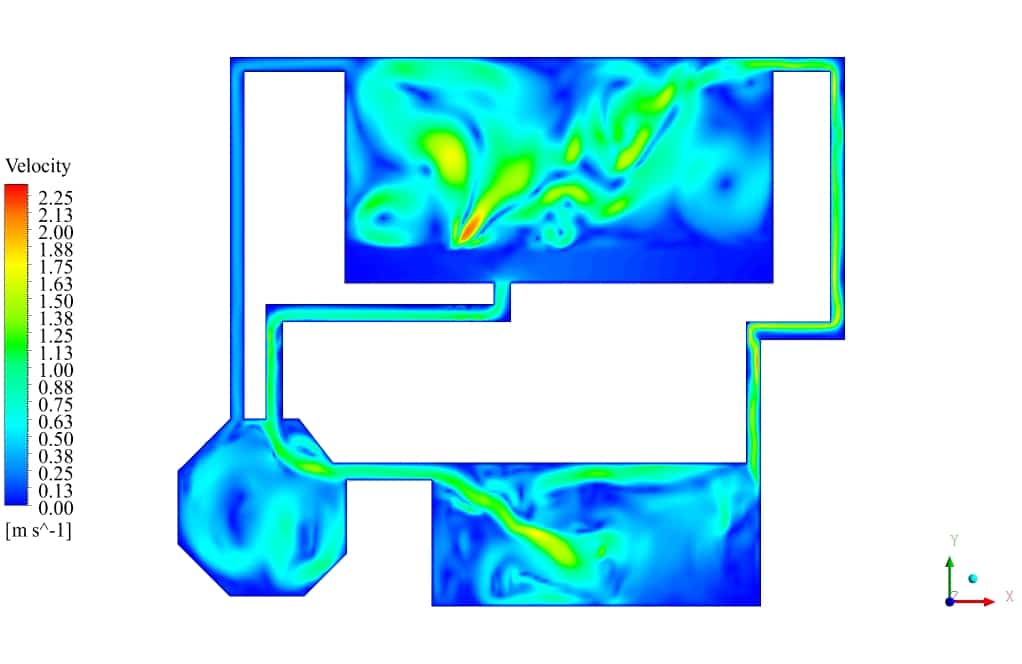
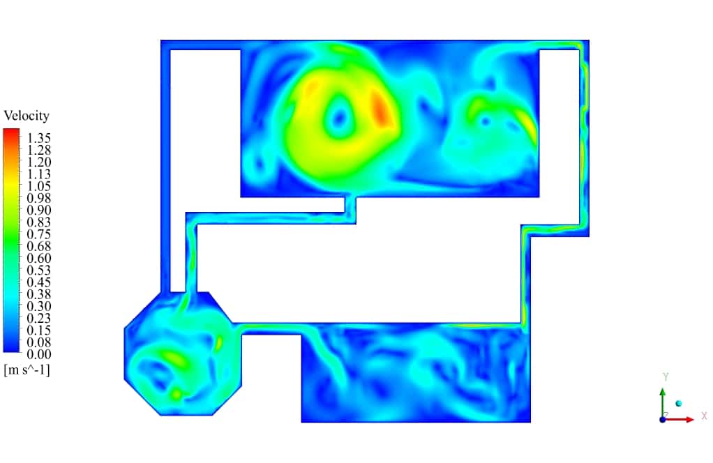
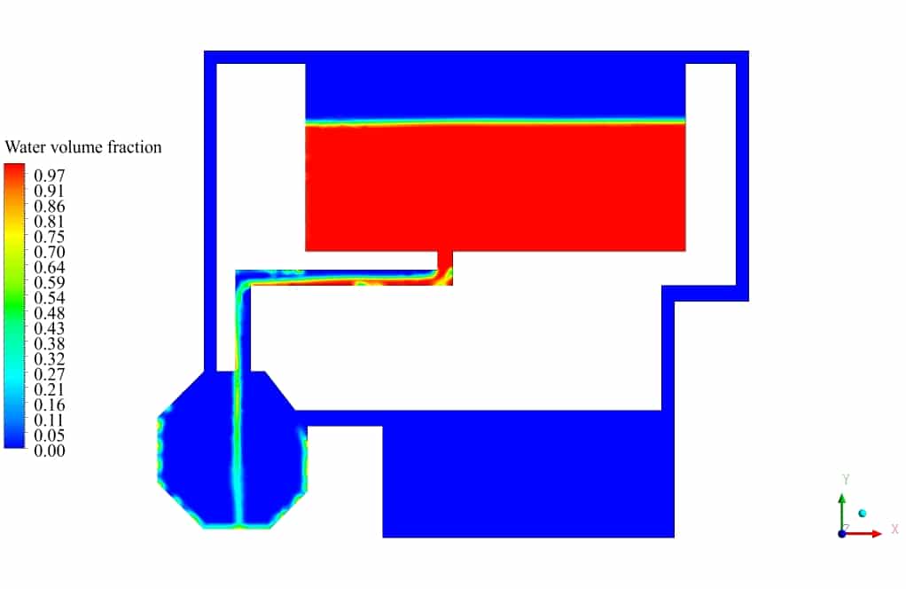
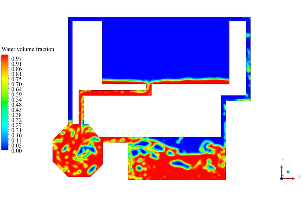
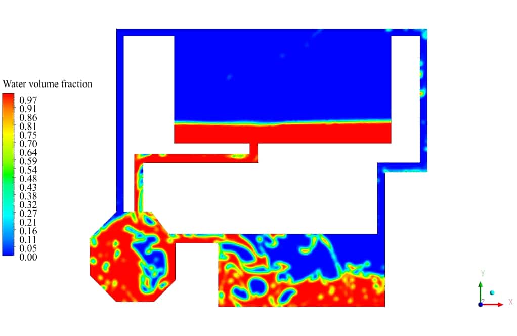
After the solution process is completed, contours of Volume fraction, Pressure, Velocity, and Streamlines are extracted and presented below. As can be observed, the water discharges from the primary tank to the secondary tank, which has insufficient volume for storing water. After a while, water starts to fill the third tank, connected to the second tank. Some pipes are for air circulation inside the tanks. This phenomenon can be seen in the velocity and streamline contours.



Rebecca –
VOF simulations are stunning! Thank you for that.