Triplex Tube Heat Exchanger by PCM, Paper Validation
$240.00 $120.00 Student Discount
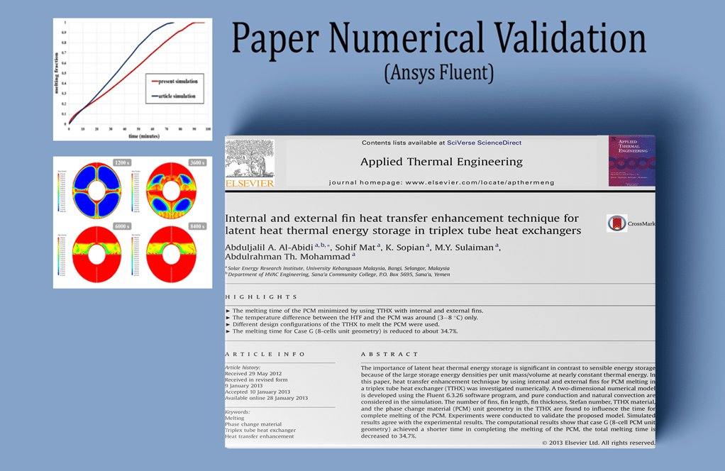
The present problem simulates heat transfer in a triplex tube heat exchanger containing phase change material (PCM) using ANSYS Fluent software. This simulation is based on the information of a reference article “Internal and external fin heat transfer enhancement technique for latent heat thermal energy storage in triplex tube heat exchangers” and its results are compared and validated with the results in the article.
Click on Add To Cart and obtain the Geometry file, Mesh file, and a Comprehensive ANSYS Fluent Training Video.To Order Your Project or benefit from a CFD consultation, contact our experts via email (info@mr-cfd.com), online support tab, or WhatsApp at +44 7443 197273.
There are some Free Products to check our service quality.
If you want the training video in another language instead of English, ask it via info@mr-cfd.com after you buy the product.
Description
Thermal Storage by PCM in a Triplex Tube Heat Exchanger CFD Simulation, Paper Numerical Validation by ANSYS Fluent
The problem simulates heat transfer in a triplex tube heat exchanger containing phase change material (PCM) using ANSYS Fluent software. This simulation is based on the information from a reference article, “Internal and external fin heat transfer enhancement technique for latent heat thermal energy storage in triplex tube heat exchangers,” Its results are compared and validated with the results in the article. The triplex tube heat exchanger consists of two coaxial tubes that divide the heat exchanger cross-section into three sections or three tubes.
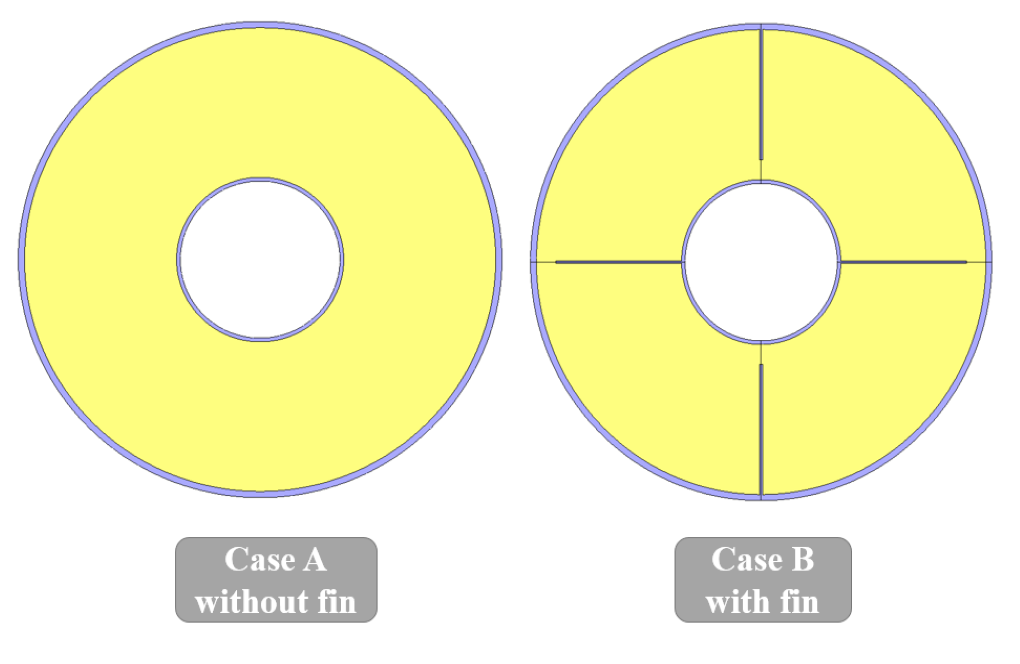
In the designed heat exchanger in this simulation, the inner and outer tubes are made of aluminum, and the space between these two tubes is where the phase change material flows. The modeling is done in two dimensions and only on a section of this heat exchanger to reduce the computational cost. Also, two different models of a cross-section of this heat exchanger have been designed, the first model has no fin (case A in the article), and the second model has four fins in its interior (case B in the article). Also, the PCM used in the simulation is RT82, whose properties are defined based on the data in Table 4 of the article. We perform Solidification & Melting module for the phase change material.
Paper Description
Thus, this material has a density equal to 770 kg.m-3, a specific heat capacity equal to 2000 j.kg-1.K-1, a thermal conductivity equal to 0.2 Wm-1.K-1 and a viscosity equal to 0.03499 kg .m-1.s-1. Also, according to the data in this table, the maximum temperature at which the solid phase temperature is (solidus temperature) is equal to 350.15 K and the minimum temperature at which the liquid phase is dominant (liquidus temperature) is 358.15 K. The Pure solvent melting heat is defined as 176,000 j.kg-1.
In this heat exchanger, the inner wall of the inner tube and the outer wall of the outer tube is considered thermal insulation; While the outer wall of the inner tube and the inner wall of the outer tube, which are in direct contact with the PCM material, has a constant temperature of 363.15 K.
Geometry & Mesh
The present model is designed in two dimensions using Design Modeler software. The model is a cross-section of a three-tube heat exchanger drawn in two modes. A circular cross-section is designed to be drawn in both models as two pipes coaxial with each other; Thus, four circles with different diameters are created. The inner and outer radii of the inner tube are 25.4 mm and 26.6 mm, respectively, and the inner and outer radii of the outer tube are 75 mm and 76 mm, respectively. In the first model, no fins are designed, but in the second model, two fins are designed to face each other on the inner tube’s outer wall, and the other two fins are designed to meet each other on the inner wall of the outer tube.
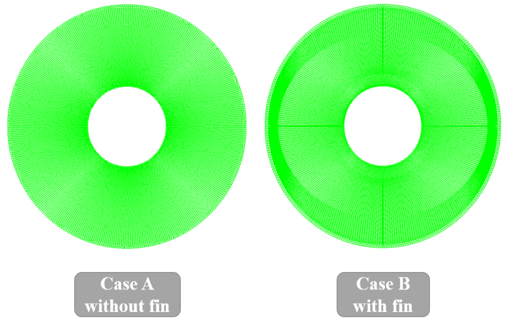
We carry out the meshing of the model using ANSYS Meshing software, and the mesh type is structured. The element number is 23908 for the first case study and 24492 for the second one with fins. The following figure shows the mesh.
Thermal Energy Storage CFD Simulation
We consider several assumptions to simulate the present model:
- We perform a pressure-based solver.
- The simulation is unsteady. Because the purpose of the present work is to study the process of Solidification and Melting over time.
- The gravity effect on the fluid is equal to -9.81 m.s-2 along the Y-axis.
The following table represents a summary of the defining steps of the problem and its solution:
| Models (PCM) |
||
| Viscous | Laminar | |
| Energy | On | |
| Solidification & Melting | On | |
| Boundary conditions (PCM) |
||
| Outer Wall of Inner Tube & Inner Wall of Outer Tube | Wall | |
| wall motion | stationary wall | |
| thermal condition | coupled | |
| temperature | 363.15 K | |
| Outer Wall of Outer Tube & Inner Wall of Inner Tube | Wall | |
| wall motion | stationary wall | |
| heat flux | 0 W.m-2 | |
| Methods (PCM) |
||
| Pressure-Velocity Coupling | SIMPLE | |
| pressure | PRESTO | |
| momentum | second-order upwind | |
| energy | second-order upwind | |
| Initialization (PCM) |
||
| Initialization methods | Standard | |
| gauge pressure | 0 pascal | |
| x-velocity & y-velocity | 0 m.s-1 | |
| temperature | 300 K | |
Paper Validation
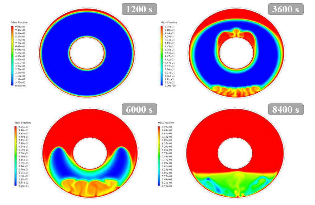
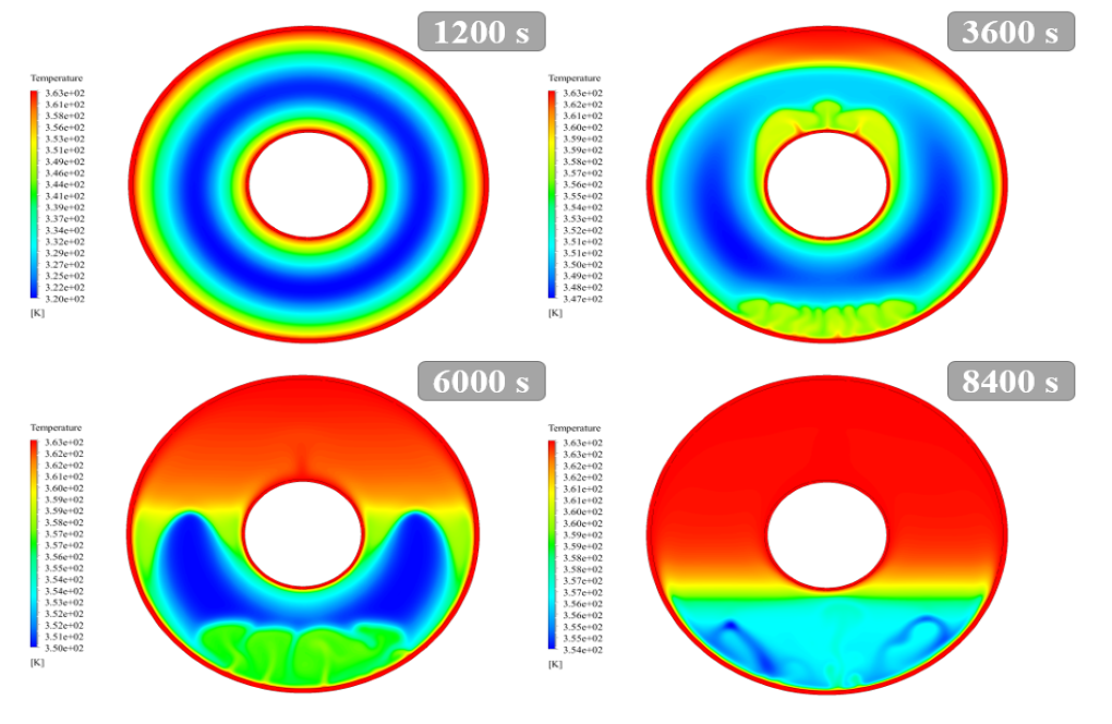
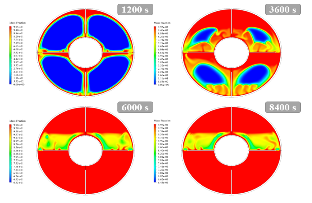
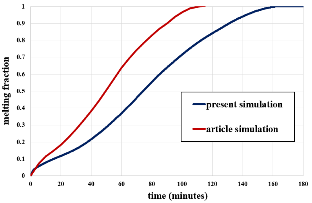
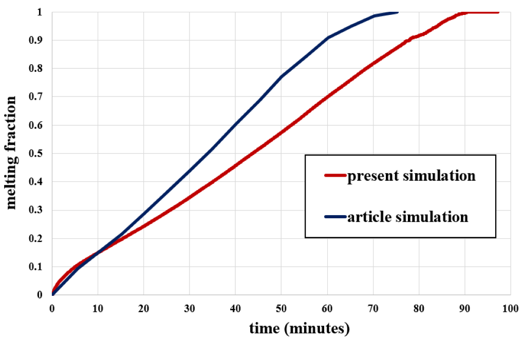
The present validation is based on the diagram in Figure 14 of the mentioned article. This diagram is related to the changes in the melting fraction over time. This diagram includes various geometric designs based on the arrangement of heat exchanger fins. In the present simulation, two case studies are examined, related to cases A and B, from Figure 2 of the paper. Based on the resulting images, it can be said that almost all of the PCM material turns into a liquid phase after a specific time.
At the end of the solution process, two-dimensional contours related to the temperature and liquid mass fraction are obtained for both models (the fin model and the without fin model). As the temperature of the phase change material increases, the amount of liquid volume fraction increases.

Miss Pearlie Goyette –
Can this simulation handle different types of PCMs?
MR CFD Support –
Absolutely! The simulation can be adapted to handle different types of PCMs by changing the material properties in the simulation setup. This makes it a versatile tool for various thermal energy storage applications.
Prof. George Lang –
What is the purpose of using phase change materials (PCMs) in this thermal energy storage simulation?
MR CFD Support –
The purpose of using PCMs in this thermal energy storage simulation is to store and release thermal energy during the process of solidifying and melting. PCMs can store high amounts of energy, making them ideal for thermal energy storage applications.
Lindsay Dickens –
I appreciate the dedication to accuracy and validation in this simulation.