Computational Fluid Dynamics Analysis of Tilt-Rotor Drone with Mesh Motion
Description
This report shows the full outcomes of a computational fluid dynamics (CFD) study that was done on a tilt-rotor drone using ANSYS The study utilised both fluid and advanced mesh motion features for the propellers and arms. The simulation was specifically designed to analyse We specifically designed the simulation to analyse the drone’s aerodynamic performance and thrust generation characteristics while implementing controlled tilt arm rotation.
We developed a custom time-dependent expression to control the tilt arm rotation, allowing for specific timing and angle adjustments during the transition phase
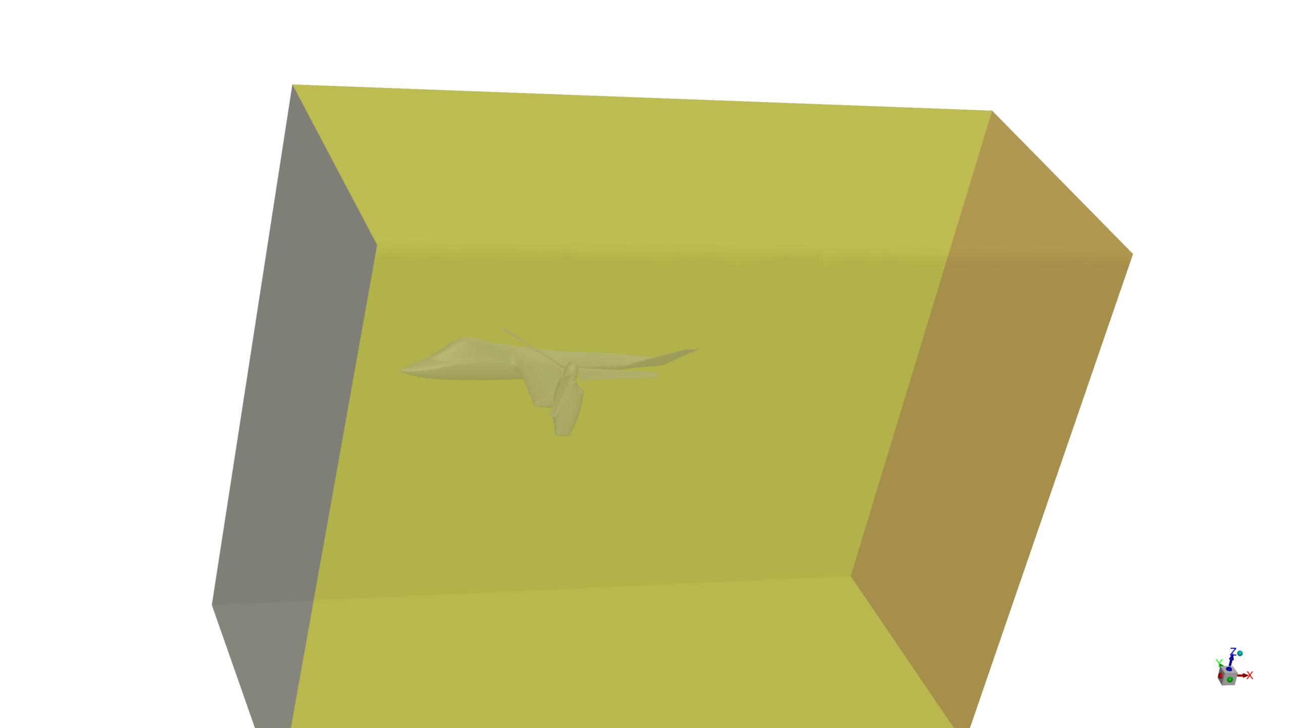
The symmetrical tilt-rotor model was meticulously created using SpaceClaim software. The complex geometry incorporated detailed representations of the arms, propellers, and main fuselage components to ensure accurate simulation results.
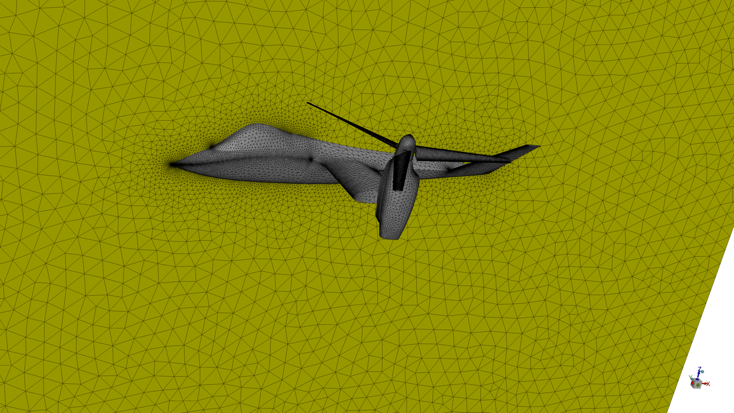
Using ANSYS Meshing, we developed a sophisticated non-conformal mesh around the propellers and arms domains. This specific mesh configuration was essential for accurately capturing the mesh motion method and ensuring computational stability during the simulation.
Methodology
The simulation utilised a pressure-based solver with transient time dependence to capture dynamic effects accurately. We implemented the k-ε RNG turbulence model with standard wall functions, operating at atmospheric pressure (101,325 Pa) to simulate real-world conditions.
We implemented the mesh motion for both arms and propellers, specifically focussing on the control of the tilt arm rotation. We developed a custom time-dependent expression to precisely control the tilt arm rotation. We designed the expression to achieve the following goals:
- Precise angle control at specific time intervals
- Programmable tilt angles from 0° to 90° within designated time frames
Results
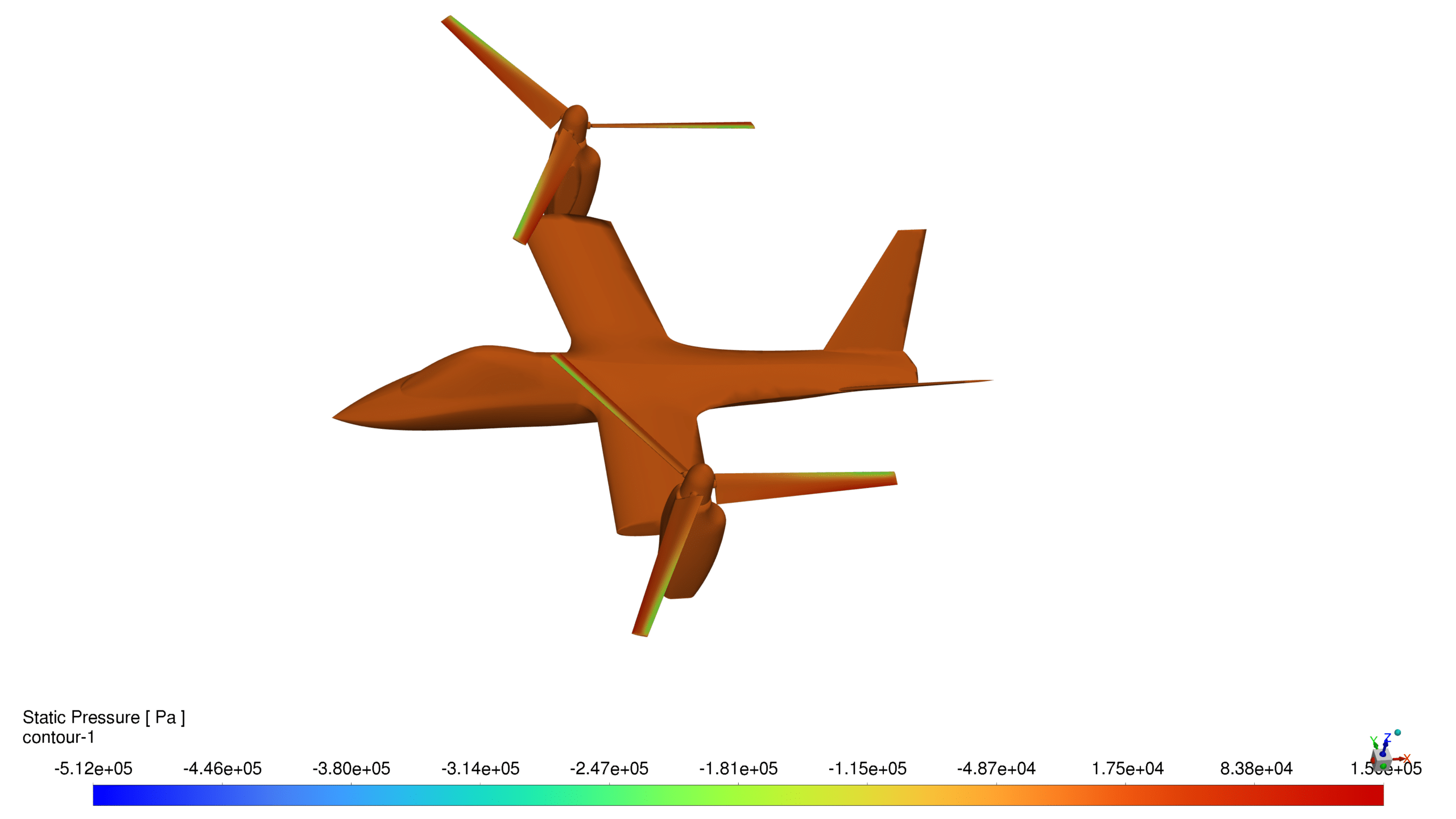
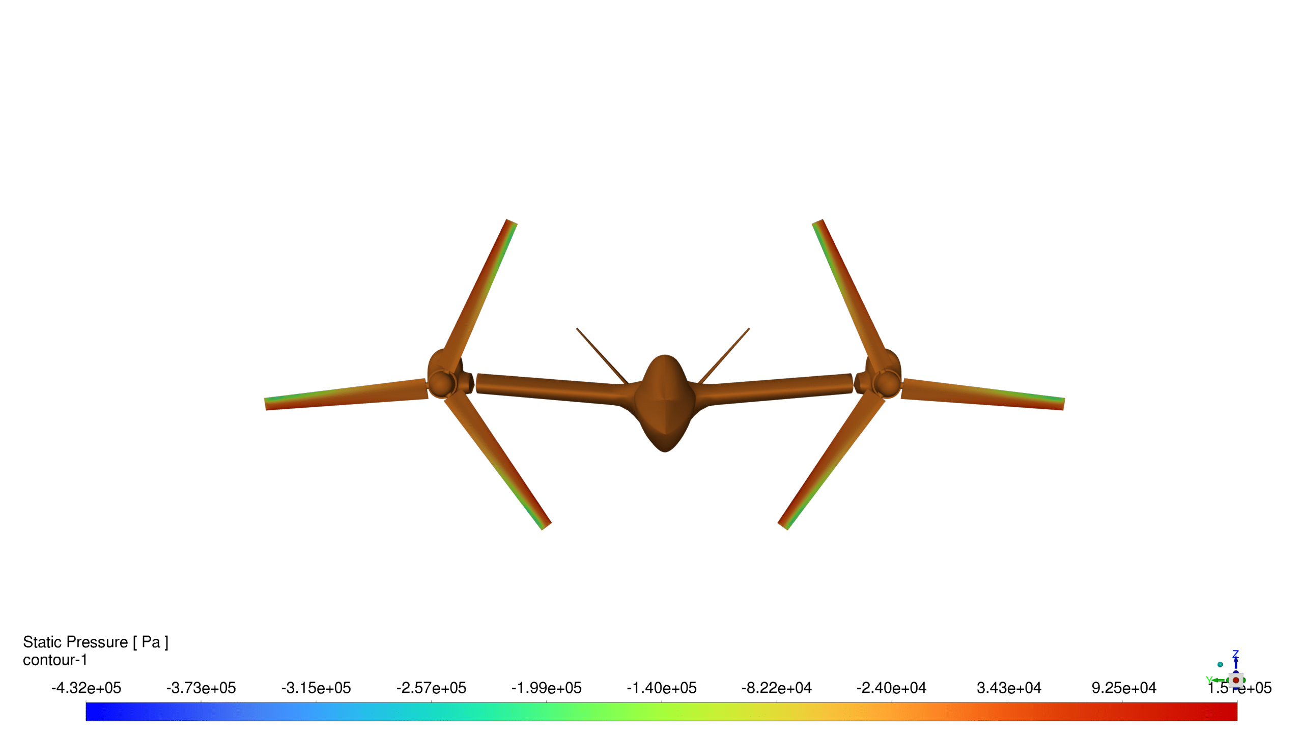
Static Pressure Distribution:
- Distinct pressure differentials were observed across propeller surfaces
- Lower pressure regions on upper surfaces confirmed effective lift generation
- Maximum negative pressure zones were concentrated at propeller tips
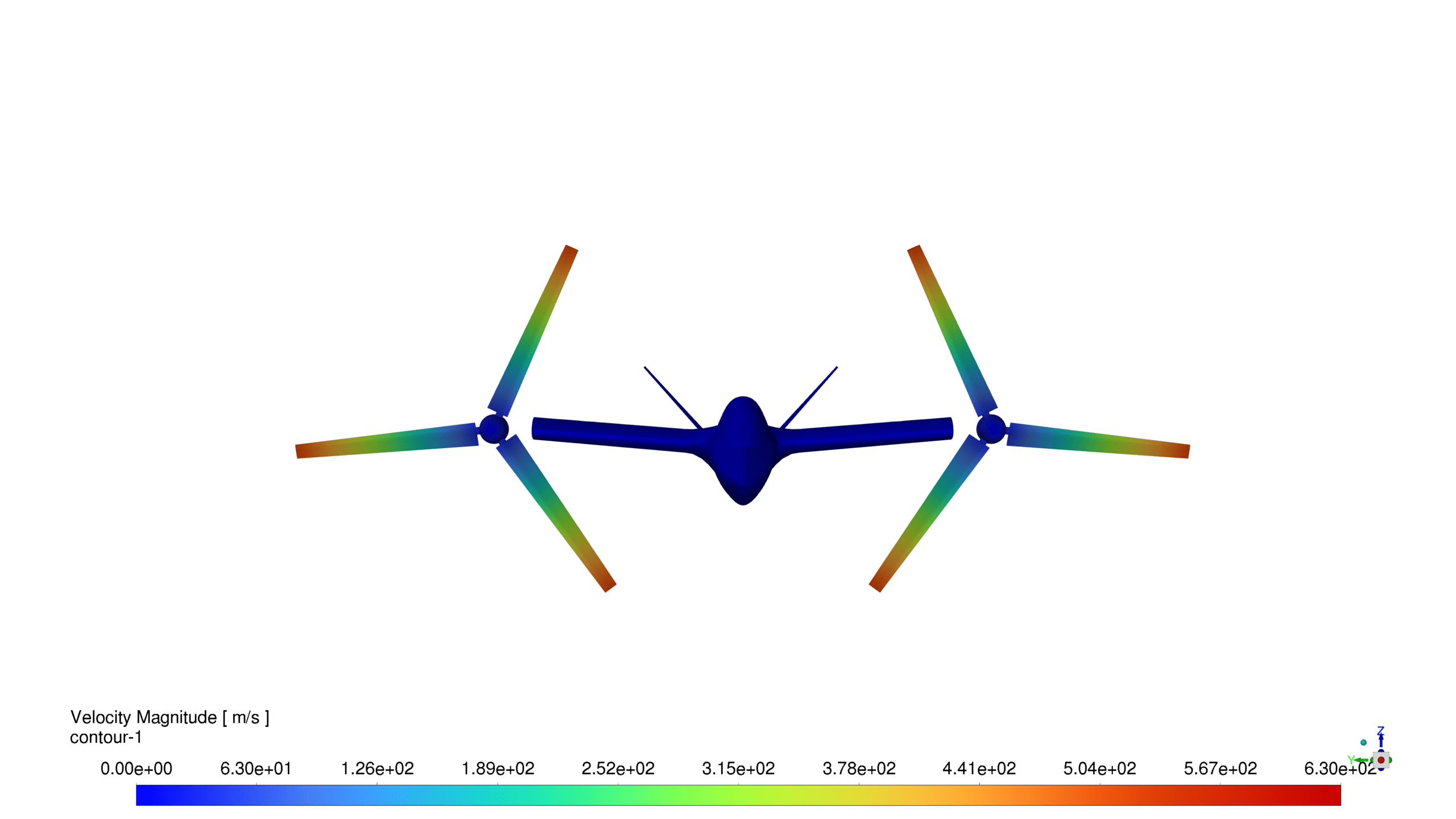
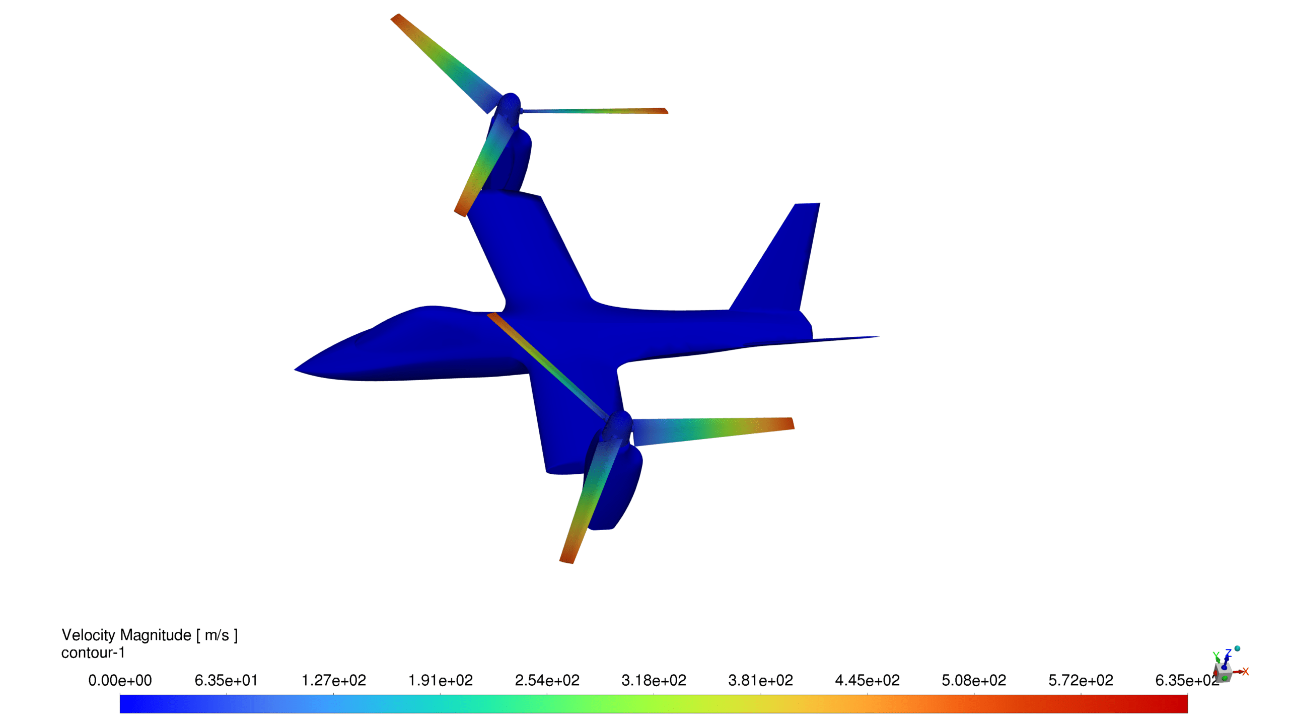
Velocity Field Analysis:
- Maximum recorded velocity: 635 m/s at propeller tips
- Operational velocity range: 0 to 635 m/s
- Clear velocity gradients across propeller rotation planes
- Uniform velocity distribution observed across symmetric propellers
- Well-defined wake formation behind propellers
Performance Metrics:
- Individual propeller thrust: 116.32 N
- Total system thrust: 465.28 N
- Symmetric thrust distribution indicating balanced performance
- High-velocity regions at blade tips confirming efficient propeller design
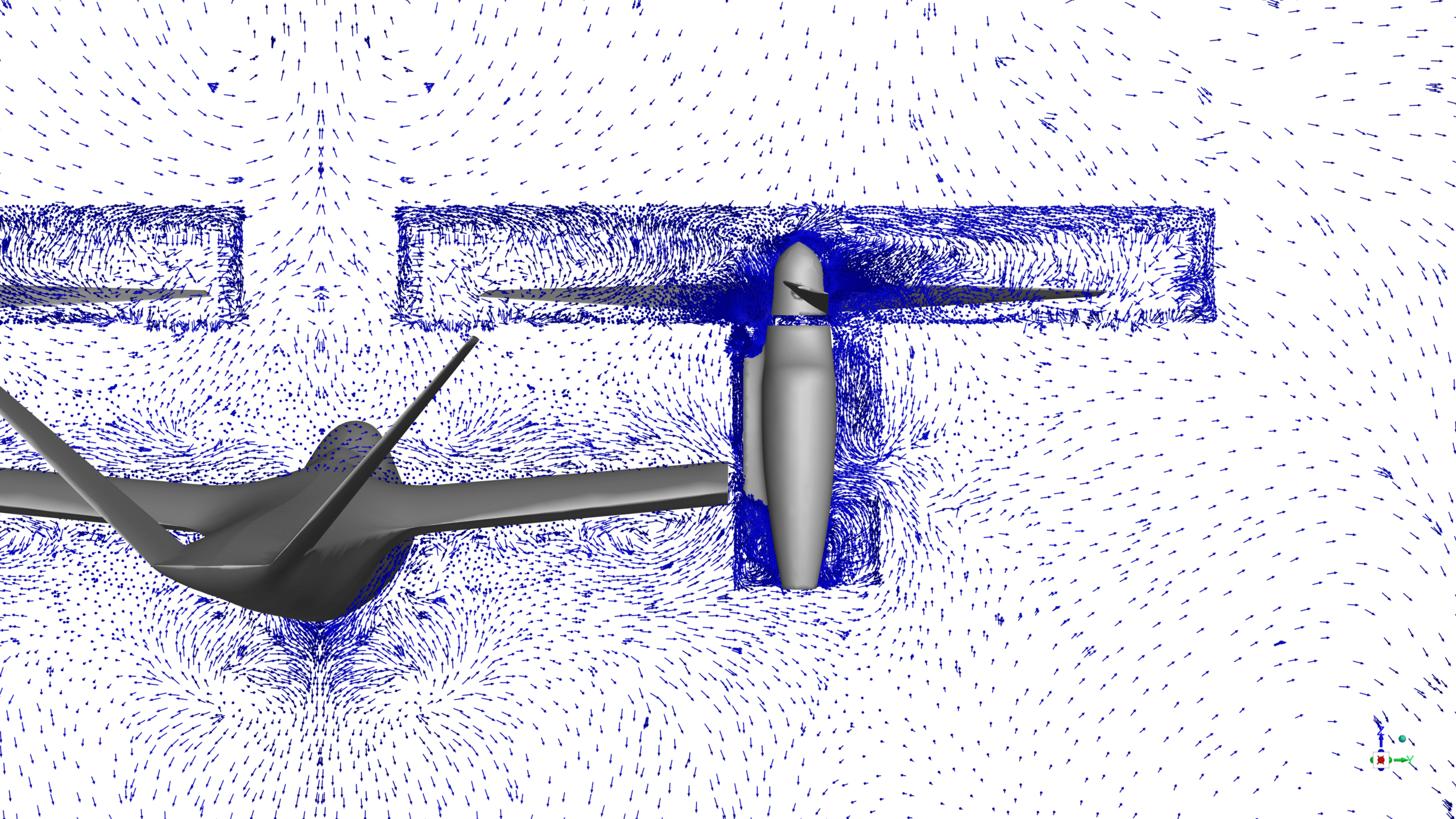
Flow Characteristics:
- Well-defined propeller wake structures
- Uniform flow distribution across the aircraft body
- Clear visualization of tip vortices
- Effective momentum transfer in propeller regions
The simulation successfully demonstrated the aerodynamic efficiency of the tilt-rotor design, with the controlled tilt arm rotation performing as expected. The propellers’ thrust of 116.32 N each shows that they can lift a lot of weight, and the even distribution of pressure shows that the aerodynamic loading is balanced. It worked well to keep things stable during transitional phases by using controlled tilt arm rotation, which allowed for precise angle control and smooth movement.


Reviews
There are no reviews yet.