Transformer Room Ventilation CFD Simulation, ANSYS Fluent Training
$140.00 $70.00 Student Discount
- The problem numerically simulates Transformer Room Ventilation using ANSYS Fluent software.
- We design the 3-D model by the Design Modeler software.
- We mesh the model with ANSYS Meshing software, and the element number equals 592411.
- We use the Heat Source and Porous Medium to consider their effect on heat transfer.
To Order Your Project or benefit from a CFD consultation, contact our experts via email (info@mr-cfd.com), online support tab, or WhatsApp at +44 7443 197273.
There are some Free Products to check our service quality.
If you want the training video in another language instead of English, ask it via info@mr-cfd.com after you buy the product.
Description
Description
The current project simulates the air conditioning inside a Transformer Room using ANSYS Fluent software. We perform this CFD project and investigate it by CFD analysis.
Transformers are devices that can transfer electrical energy between two or more windings through electromagnetic induction. These transformers are placed in a room due to safety issues, in which an optimal air conditioning system should be used where the transformers are stored.
These transformers are considered a kind of heat source that affects the ambient air temperature. The present model is designed in three dimensions using Design Modeler software. The model consists of a two-part room with a thin membrane.
This room has 10 air inlet ducts through the top and 4 ducts for air outlets on the side walls. In this room, 3 transformers are designed as heat sources. A porous (louver window) medium is also used for each airflow outlet.
The meshing of the model has been done using ANSYS Meshing software. The element number is 592411.
Transformer Room Methodology
In this project, a two-piece room is designed with a divider in the middle, made by a wooden wall with thermal conductivity of 0.173 W/m.K. Inside the room, there are three transformers made of aluminum with thermal conductivity of 202.4 W/m.K, each of which has a constant heat source equal to 6060.606 W/m3.
The airflow enters the room through ducts designed on top of one of the transformer room walls (with speeds equal to 1,531 m/s and 2.04 m/s, with an angle equal to 45 degrees and at a temperature equal to 303.15 K). It exists through the outlets (with a pressure equal to atmospheric pressure).
For better distribution of hot air flow out of the room, louver windows connected to the exhaust ducts are used, each of which has a porosity coefficient equal to 0.6 and a viscosity resistance (1/ permeability) of 211100000 1/m2.
Also, convection heat transfer around the walls of the transformer is assumed. The fluid bulk temperature equals 300 K, and the heat transfer coefficient equals 24 W/m2.K.
The standard k-epsilon model is used to solve turbulent fluid equations. Also, the energy equation has been enabled to account for the temperature change within the computational domain.
Transformer Room Conclusion
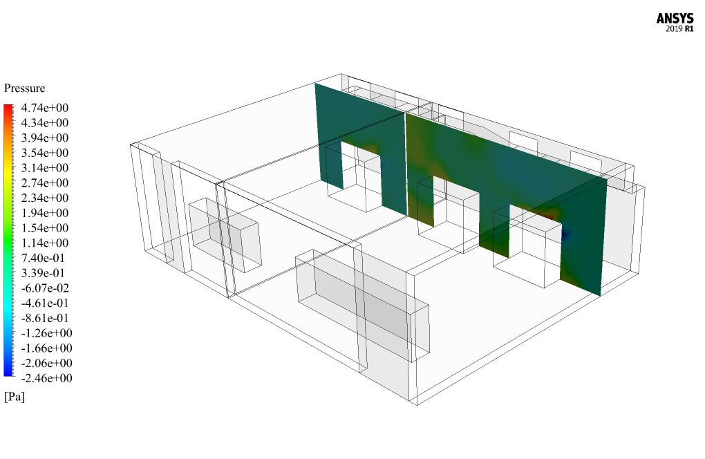
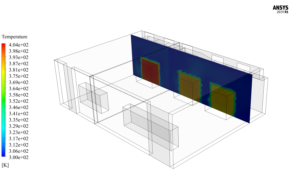
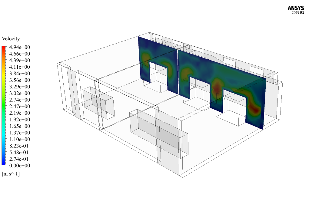
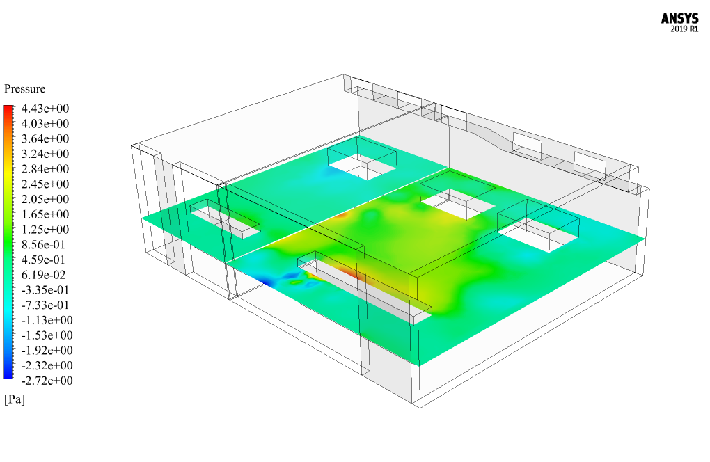
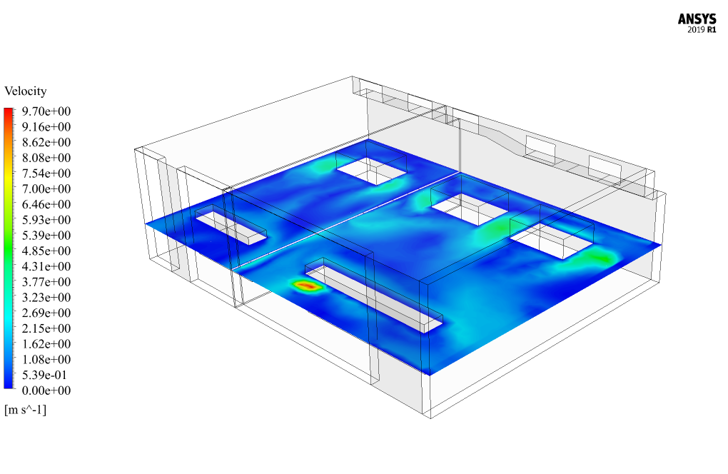
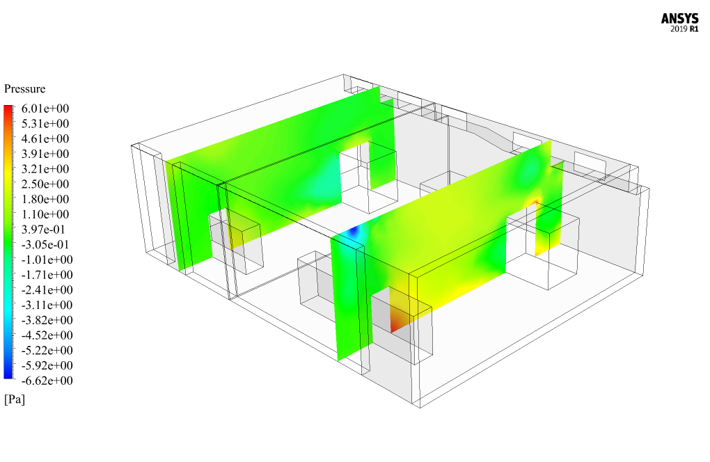
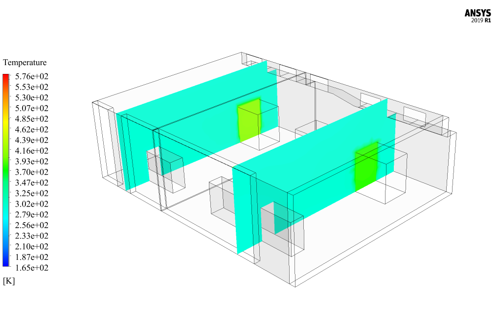
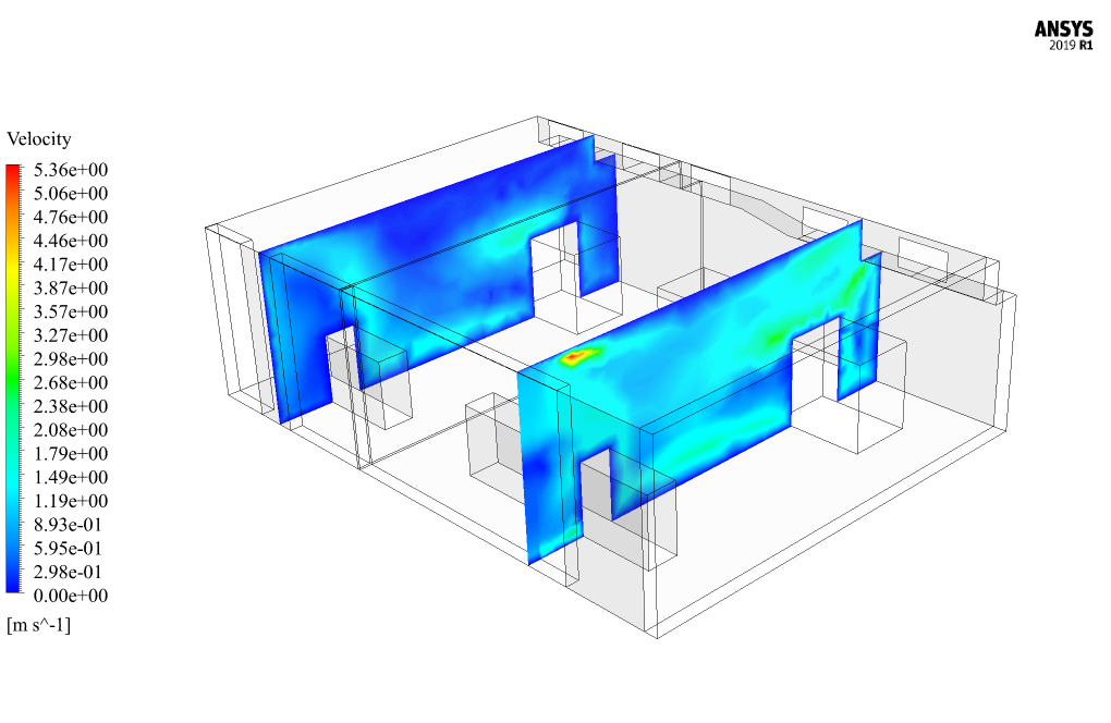
At the end of the solution process, two-dimensional contours related to pressure, temperature, and velocity were obtained. As seen in the temperature contour, the overall temperature will decrease due to the forced convection and airflow motion within the transformer room.



Angie Lesch IV –
I really enjoyed the cleanness and detail of the methodology in this training material. It’s impressive to visualize temperature contours and understand how the cooling system impacts the overall temperature in the transformer room.
MR CFD Support –
Thank you for your positive feedback! We’re delighted to hear that you appreciate the clear methodology and detail provided in the training material. The temperature contours are indeed valuable for comprehending the effectiveness of the air conditioning system in maintaining the transformer room’s temperature. If you have more questions or need further assistance with your simulations, please feel free to reach out to us.
Ruben Schaefer IV –
The description mentions the use of louver windows connected to the exhaust ducts. I’m curious, how did the louvers’ porosity and viscosity resistance values affect the ventilation effectiveness in the transformer room?
MR CFD Support –
The louver windows’ porosity allowed for a controlled exertion of airflow, ensuring space remained well-ventilated without creating turbulence detrimental to system efficiency. The viscosity resistance of 211100000 1/m2 meant air faced significant resistance passing through, maintaining a steady and managed flow. These values contributed to a stable and efficient ventilation by distributing the hot air evenly, aiding in optimal transformer cooling.
Alfred Bartoletti V –
I’m extremely pleased with how the Transformer Room Ventilation CFD Simulation using ANSYS Fluent helped to understand the effects of air conditioning on the temperature distribution around the transformers. The visuals provided with the temperature and flow contours were insightful.
MR CFD Support –
Thank you for your positive feedback! We’re glad to hear that the Transformer Room Ventilation CFD Simulation met your expectations and provided you with clear insights. Your satisfaction with the visuals and the understanding you gained about temperature distribution is exactly what we aim for. If you have any more questions or need further assistance, please do not hesitate to contact us.
Dr. Glen O’Keefe –
I enjoyed learning from the ‘Transformer Room Ventilation CFD Simulation, ANSYS Fluent Training’. The level of detail in both the simulation methodology and analysis exceeded my expectations. It was quite informative to see how important ventilation is to safety and equipment efficiency.
MR CFD Support –
Thank you for your positive feedback! We’re delighted to hear that the ‘Transformer Room Ventilation CFD Simulation, ANSYS Fluent Training’ was informative and exceeded your expectations. Ensuring a practical understanding of the importance of ventilation in such settings is a priority for us, and we’re glad it reflected in our training. If there’s anything else you’d like to learn about or insights you need, feel free to reach out!
Tara Hodkiewicz –
I was impressed with the level of detail in the simulation of the transformer room thermal management design. Nice work demonstrating the effect of forced convection and the airflow distribution!
MR CFD Support –
Thank you for your positive feedback! We’re glad to hear you appreciated the detail and effort that went into this CFD simulation of the transformer room. If you have any more questions or need further information, feel free to reach out to us.
Dr. Joannie Thiel –
I completed the Transformer Room Ventilation tutorial. The instructions were really clear, step-by-step approach made mastering complex topics much more manageable. Kudos to the content team for simplifying such intricate CFD analysis!
MR CFD Support –
Thank you for your positive feedback! We’re glad to hear our tutorial on Transformer Room Ventilation using ANSYS Fluent was helpful for you. If you have any further questions or need assistance in the future, feel free to reach out to us. Good luck with your future CFD analyses!
Sydni Waelchi –
I’ve learned a lot from this Transformer Room Ventilation CFD Simulation. The explanation of the setup and the conclusions drawn were enlightening. The practical application of the k-epsilon model in maintaining temperature within safe limits around heat sources like transformers was particularly interesting. I will recommend this course to colleagues looking for comprehensive CFD analysis training.
MR CFD Support –
Thank you for your positive review! We’re glad you found the Transformer Room Ventilation CFD Simulation educational, and it’s great to hear that our detailed explanations have been helpful. Your recommendation is highly appreciated, and we’re pleased to know that our course will be useful to others as well. If you have further questions or need more insights in the future, feel free to reach out!
Ms. Greta Welch V –
Absolutely impressive project detailing the transformer room ventilation! The balance between necessity and innovation in the engineering approach for managing temperatures within critical infrastructure is spot on. Effective thermal management is crucial, and it seems that this simulation delivers all the right computational insights to ensure the integrity and performance of the transformers are maintained. Well done on crafting such a precise and practical analysis!
MR CFD Support –
Thank you for your positive feedback! We are thrilled to hear that you found the Transformer Room Ventilation CFD simulation both impressive and practical. Ensuring the integrity and performance of critical infrastructure through effective thermal management is indeed vital. We take pride in delivering detailed analyses and insights that can help design efficient ventilation systems. If you need any more information or assistance with other simulations, feel free to reach out to us.
Zakary Hill –
I’ve learned so much about CFD from this course. The progressive difficulties really pushed my understanding of the subject—excited to apply this in practical scenarios!
MR CFD Support –
Thank you for your positive feedback. We are thrilled to hear that our course has enriched your understanding of CFD and that you feel well-prepared to apply your knowledge in real-life applications. Keep up the great work!
Neal Ritchie –
The training material is superb! The step-by-step process with developed methodology gives deep insight into conducting a real CFD simulation for a transformer room. It helped me comprehend the complications involved in ventilating electrical equipment spaces efficiently.
MR CFD Support –
Thank you for your kind words! We’re thrilled to hear that our training material on the Transformer Room Ventilation CFD Simulation was helpful to you. It’s great that the methodology and step-by-step guide provided you with a deeper understanding of CFD analysis. We appreciate your feedback and are happy to have contributed to your learning experience.
Ricardo Kreiger –
The project presentation is clear and informative. It really helps to understand how essential proper ventilation is in maintaining the performance and safety of transformer rooms. Good job on the simulation and providing detailed insights into the airflow dynamics around the transformers!
MR CFD Support –
Thank you for your positive feedback! We’re delighted to know that our detailed simulation and presentation of the Transformer Room assisted you in understanding the significance of ventilation systems. Should you have any more questions or need further explanation, feel free to reach out.
Robb Franecki –
The details provided are awe-inspiring! Could you tell me more about how the porous media in the ventilation system is modeled to affect the airflow?
MR CFD Support –
In this CFD simulation, the porous media, representing the louver windows, is defined with a porosity coefficient and a viscosity resistance. The porosity coefficient equates to the accessible volume fraction for the flow, while the viscosity resistance is the inverse of permeability, dictating how easy it is for the air to pass through the porous medium. Together, these factors accurately simulate the impact of the louver windows on airflow distribution within the transformer room.