Turbine Blade Cooling CFD Simulation, ANSYS Fluent Training
Free
- The problem numerically simulates Turbine Blade Cooling using ANSYS Fluent software.
- We design the 3-D model by the Design Modeler software.
- We Mesh the model by ANSYS Meshing software, and the element number equals 10154723.
- We activate Energy Equation and apply thermal boundary conditions on the turbine blades.
To Order Your Project or benefit from a CFD consultation, contact our experts via email (info@mr-cfd.com), online support tab, or WhatsApp at +44 7443 197273.
There are some Free Products to check our service quality.
If you want the training video in another language instead of English, ask it via info@mr-cfd.com after you buy the product.
Description
Description
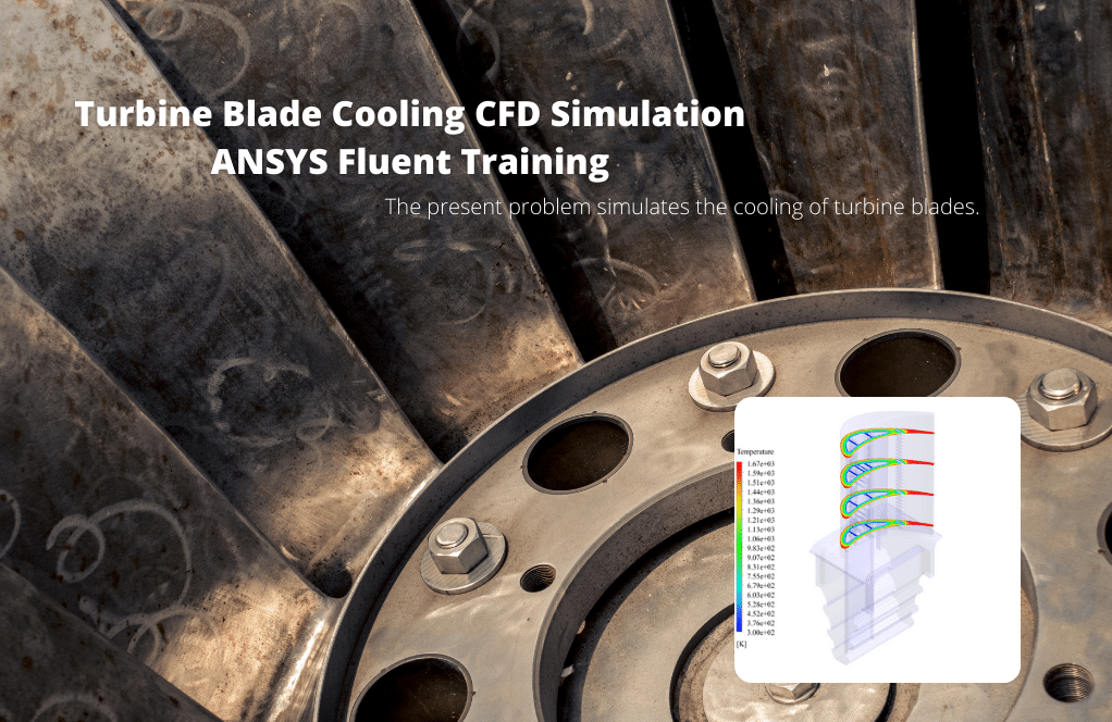
The present problem simulates the Cooling of Turbine Blade by ANSYS Fluent Turbine. We perform this CFD project and investigate it by CFD analysis.
To simplify the problem model, considering the symmetrical structure of the turbine body and its blades, only one blade is simulated. The main purpose of the problem is to investigate the temperature distribution and changes in thermal energy on the body and turbine blade.
Therefore, the process of simulating the model and defining the boundary conditions of the model is performed in such a way that the fluid behavior is focused on heat transfer.
The cooling process in this model is based on the definition of cool airflow in an empty space in the inner walls of the blade. These inner walls have a series of holes to increase the contact surface with the cold flow and thus increase the cooling process.
The present 3-D model is drawn using the CATIA software and then imported into the Design Modeler software. The meshing of the present model has been done using ANSYS Meshing software. The mesh type is unstructured and the element number is equal to 10154723.
Turbine Blade Methodology
The boundary condition of heat transfer has been used on the surfaces of the outer and inner walls of the blade. The outer surface of the blade and its lower body, which are under the hot working airflow of the system, have a transfer coefficient of 200 watts per cubic meter and a temperature of 1672 Kelvin.
However, the inner surface of the blade, which is cooled by the cold airflow, has a heat transfer coefficient of 200 watts per cubic meter under a cold flow of 300 Kelvin.
Turbine Blade Conclusion
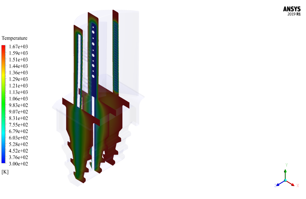
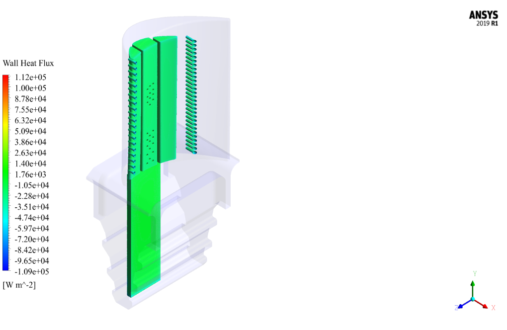
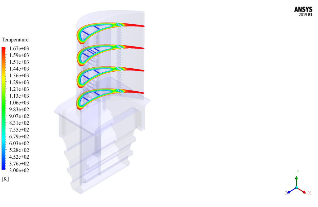
After the solution process is complete, 2-D and 3-D temperature contours are obtained in the space between the outer wall of the blade (in contact with the hot flow) and the inner wall of the blade (in contact with the cooling flow).
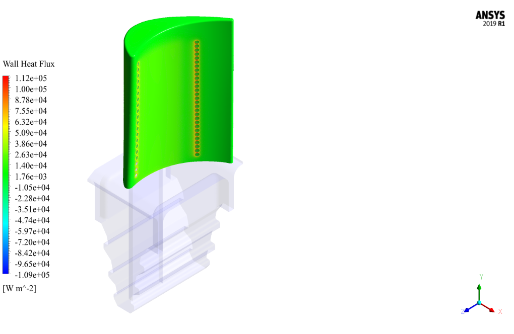
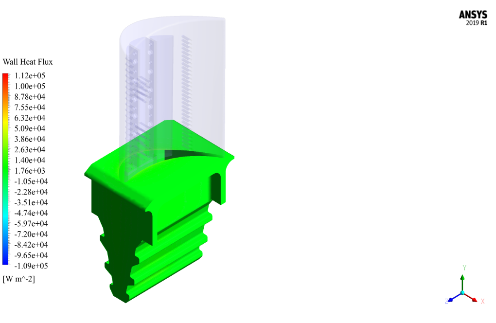
Also, the amount of heat transfer coefficient is obtained on the inner and outer walls of the blade and the blade base.
The two-dimensional contours in the XZ section are drawn at different distances of 0.004, 0.016, 0.028 and 0.04 meters from the upper surface of the blade base, as well as in the XY section at different distances

Misty Feest –
How are the results of the simulation visualized?
MR CFD Support –
The results are visualized using contour plots of temperature and velocity, as well as pathlines of the cooling fluid.
Kylie Mills –
This simulation is a breakthrough in the field of turbine cooling!
Oleta Hagenes Jr. –
It was incredible. The way the content was expressed and coherent was excellent. Thank you, dear master.
Francisca O’Hara Sr. –
Can I contribute to this simulation?
MR CFD Support –
We are open to contributions! Please share your ideas or suggestions.
Prudence Hills –
This CFD simulation was comprehensive and the final report was both detailed and easy to grasp!
MR CFD Support –
Thank you for your positive feedback! We are delighted to hear that you found our CFD simulation and report on Turbine Blade Cooling not only detailed, but also easily understandable. We appreciate your review and are glad our efforts are well received.
Oceane Heidenreich II –
Excellent, thanks to MR-CFD
Meagan Zemlak III –
Are the simulation results from this Turbine Blade Cooling CFD project validated against experimental or numerical data?
MR CFD Support –
In this provided description, there is no mention of validation against experimental or other numerical data. To assure accuracy, simulation results would typically be compared with such data when available.
Antoinette Frami –
Is there any analysis available regarding the efficiency of the turbine blade cooling system and how different variables impact this efficiency?
MR CFD Support –
In our simulation, we focus on examining the temperature distribution and thermal energy changes on the body and turbine blade. While direct efficiency calculations have not been specified in the provided training tutorial, analyzing the temperature contours and heat transfer coefficients allows for extrapolation of cooling efficiency. Understanding the relationship between surface temperatures, internal cooling airflow, and materials contributes to evaluating the cooling system’s performance. We encourage users to explore how variations in parameters such as external heat flux, internal flow rate, and material properties might affect cooling efficiency within the simulation’s framework.
Ms. Graciela Kutch PhD –
Can this simulation help in optimizing the cooling flow rate to enhance the blade cooling without compromising the blade’s material integrity?
MR CFD Support –
Yes, the simulation provides detailed temperature distribution and heat transfer coefficients, which can be used to assess the cooling flow effectiveness. It’s possible to make adjustments to the cooling flow rate and analyze the subsequent changes in heat transfer to find an optimal balance for effective cooling without causing thermal stress that could compromise material integrity.
Leonie Marks –
The explanations on the cooling airflow inside the blade’s inner walls are fascinating! The details on the heat transfer process convey a sense of precision and robust engineering behind the simulation. Keep up the great work!
MR CFD Support –
Thank you so much for your positive feedback! We’re delighted to hear that you found the turbine blade cooling simulation details informative and engaging. It’s great to know that the effort we put into describing the engineering and precision of our simulations is appreciated. If you have any further questions or need assistance with similar projects, please feel free to reach out.
Mrs. Delphia VonRueden DDS –
Is the simulated airflow within the hollow section of the turbine blade able to reliably demonstrate how the blade will perform under actual operating temperatures and conditions?
MR CFD Support –
Yes, the CFD simulation’s primary aim is to realistically replicate the cooling airflow within the turbine blade under specified operating conditions, giving insights into the performance of the cooling strategy at actual temperatures and conditions experienced during turbine operation.
Yoshiko Klein –
Was there an evaluation of the effectiveness of the cooling in different sections of the blade based on the simulation results?
MR CFD Support –
In the simulation for the Turbine Blade Cooling project using ANSYS Fluent, effectiveness of the blade cooling is evaluated through multiple 2-D and 3-D temperature contours. These results quantify the temperature gradients and allow the assessment of how efficiently the cool airflow performs within the internal passages, specifically on the inner and outer walls as well as along the length of the blade.
Sienna Medhurst –
The training has helped me tremendously in visualizing and understanding how the cooling process of a turbine blade is simulated. I am intrigued by how the inner walls are designed with holes to increase the heat transfer area. Did the training also cover how the presence of these holes affects the overall structural integrity of the blade during operation?
MR CFD Support –
The main focus of this CFD project is on the heat transfer and cooling aspects of the turbine blade, and while the presence of holes aims to increase the efficiency of cooling, the training material seems to concentrate primarily on thermal aspects rather than structural integrity. Structural analysis may be covered separately or perhaps integrated into more advanced training sessions dedicated to holistic design evaluations that take into account both thermal and structural performance factors.
Miss Dessie Marvin V –
The description mentions that the boundary conditions for the inner and outer walls of the blade have a transfer coefficient of 200 watts per cubic meter. Could you explain how this transfer coefficient impacts the cooling process of the turbine blade in the simulation?
MR CFD Support –
Admin Response here.
Dr. Barry Daugherty Jr. –
Are the holes on the inner walls of the blade modeled directly in the simulation, and how does their presence affect the cooling effectiveness?
MR CFD Support –
Yes, the holes on the inner walls of the blade are directly modeled within the simulation to accurately evaluate their impact on the cooling process. Their presence increases the contact surface area with the cool airflow, promoting improved heat transfer and consequently more effective cooling of the turbine blade.
Icie Breitenberg –
I’m curious about the heat transfer on the outer wall of the blade. Is it homogenous across the surface or does it vary significantly in different areas due to the airflow and cooling holes?
MR CFD Support –
The heat transfer on the outer wall of the blade typically shows variations across the surface. This variation is due to several factors, such as the non-uniform hot working airflow over the blade, the presence of the cooling holes, and the complex geometry of the blade itself. In this simulation, heat transfer is influenced by the local flow characteristics and distribution of the cooling holes, resulting in non-homogeneous thermal profiles on the blade surface.
Krystel Greenholt V –
Is there any explanation provided for how the cool airflow in the holes contributes to the efficiency of the cooling process?
MR CFD Support –
Yes, the provided materials would include a detailed explanation of how the cool airflow through the holes in the inner walls of the turbine blade enhances the cooling efficiency. This is achieved by increasing the contact surface area between the cool airflow and the hot surfaces within the blade. By doing so, the cool airflow extracts more heat from the turbine blade, thus improving the cooling process efficiency.
Twila Pfannerstill –
I’m thoroughly impressed by the level of detail in this cooling simulation. The methodology seems well-thought-out and the element number in the mesh is impressive!
MR CFD Support –
Thank you very much for acknowledging the effort put into the turbine blade cooling simulation. We always aim to provide the most detailed and accurate simulations possible. Your feedback is truly appreciated!
Ms. Eryn Powlowski PhD –
What is the benefit of using CFD for analyzing turbine blade cooling?
MR CFD Support –
CFD allows for detailed analysis of the cooling performance of a turbine blade, which can provide valuable insights for design optimization and performance assessment.
Rachelle Fritsch –
I’m really impressed with the detail and depth of the turbine blade cooling simulation! The accuracy of the temperature distribution results must provide invaluable insights for designing more efficient cooling mechanisms.
MR CFD Support –
Thank you for your positive feedback on our turbine blade cooling simulation! We’re glad to hear that you appreciate the level of detail in our analysis. It’s our goal to provide comprehensive and accurate insights that assist in the design of more effective cooling strategies for turbine blades.
Aida Jenkins Sr. –
The learning module on Turbine Blade Cooling was comprehensive and the temperature distribution results were fascinating!
MR CFD Support –
Thank you for your positive feedback! We are thrilled that you found our Turbine Blade Cooling simulation tutorial comprehensive and insightful. We strive to provide detailed and accurate CFD analysis to help our customers understand complex simulations. If you have any further inquiries, feel free to reach out. We’re here to support your learning journey.