Turbocharger Performance CFD Simulation, ANSYS Fluent Training
$160.00 $80.00 Student Discount
To Order Your Project or benefit from a CFD consultation, contact our experts via email (info@mr-cfd.com), online support tab, or WhatsApp at +44 7443 197273.
There are some Free Products to check our service quality.
If you want the training video in another language instead of English, ask it via info@mr-cfd.com after you buy the product.
Description
Turbocharger Performance CFD Simulation, ANSYS Fluent Training
Introduction
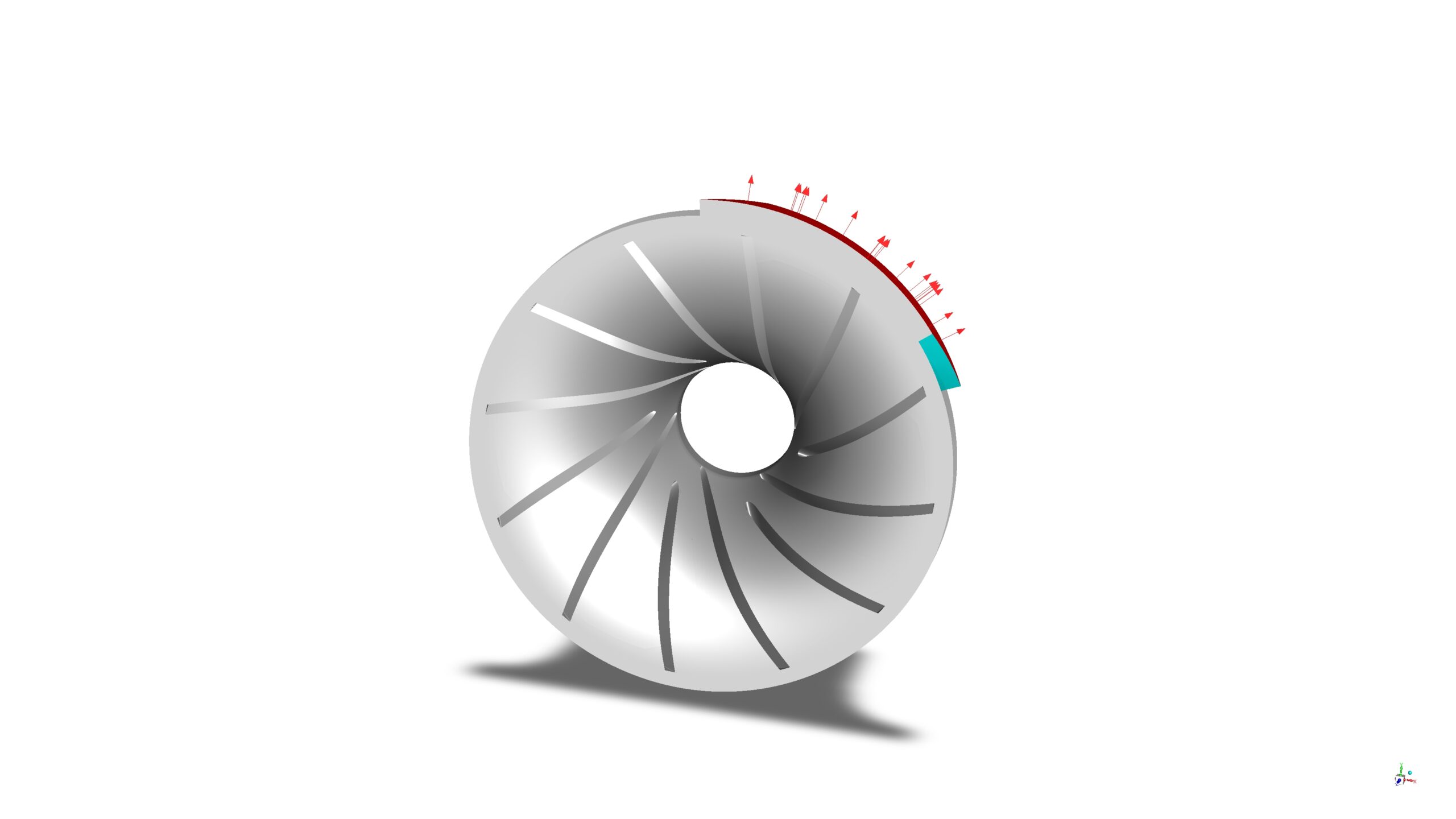
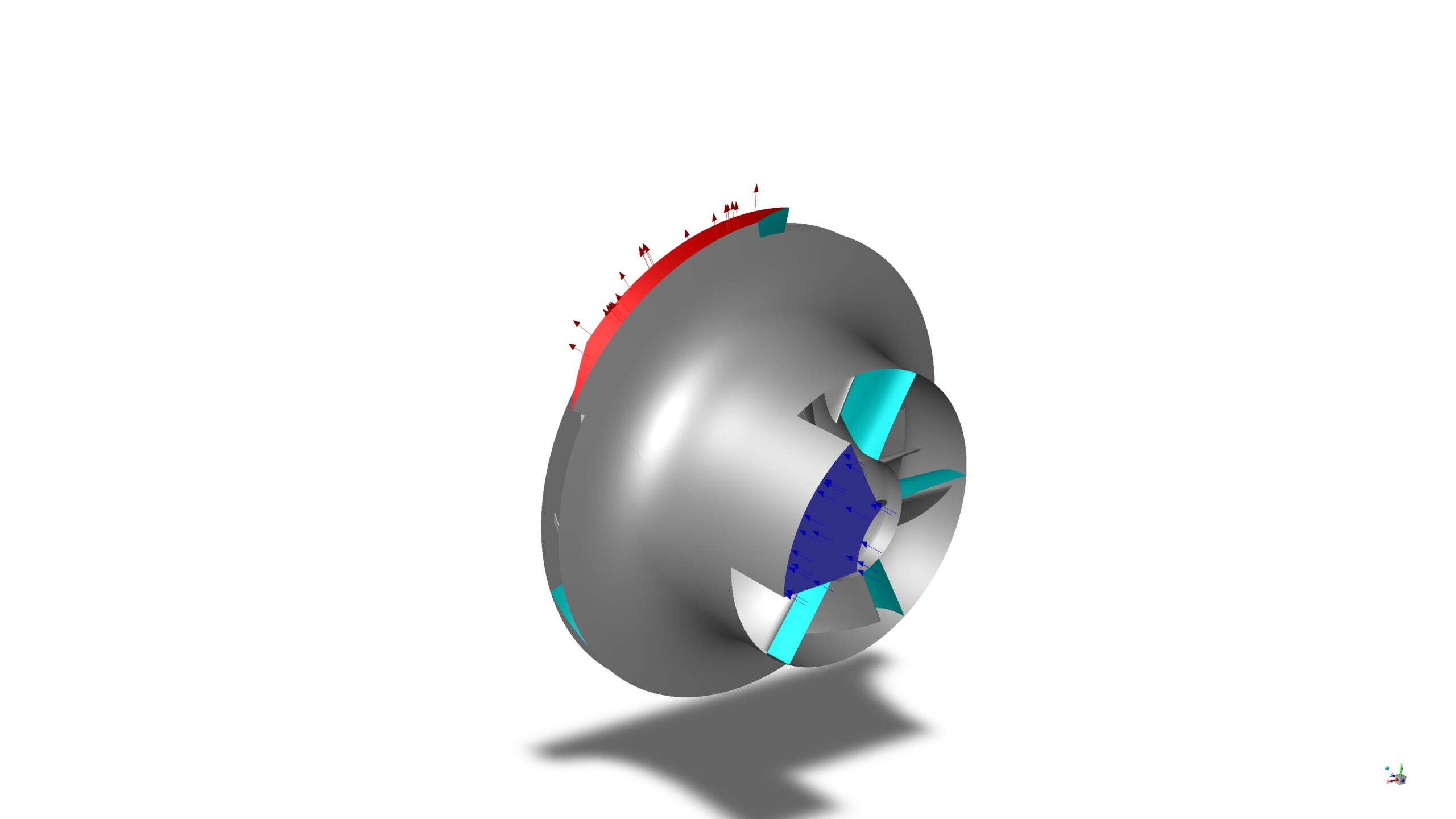
Turbochargers play a crucial role in improving engine performance and efficiency in various applications. This study explores the fluid dynamic behavior and thermal characteristics of a turbocharger using Computational Fluid Dynamics (CFD) analysis. The simulation focuses on a one-sixth periodic section of the turbocharger, capturing the complex flow patterns and temperature distributions within the device.
The primary objective of this research is to analyze the effects of the turbocharger’s geometry on flow patterns, pressure distribution, and temperature gradients. By simulating the airflow through the turbocharger under specified pressure conditions, we aim to understand the device’s performance and its impact on overall engine efficiency.
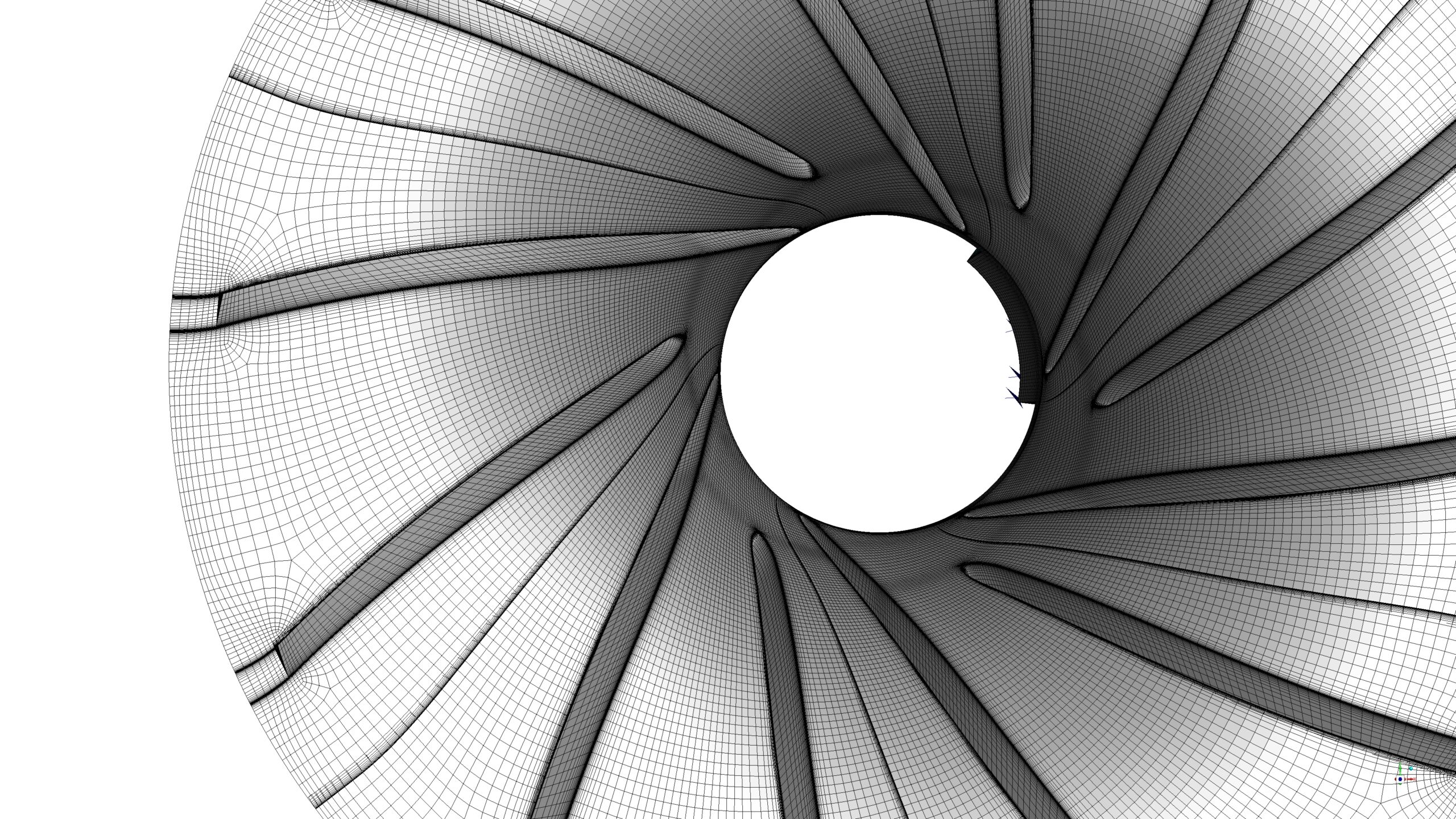
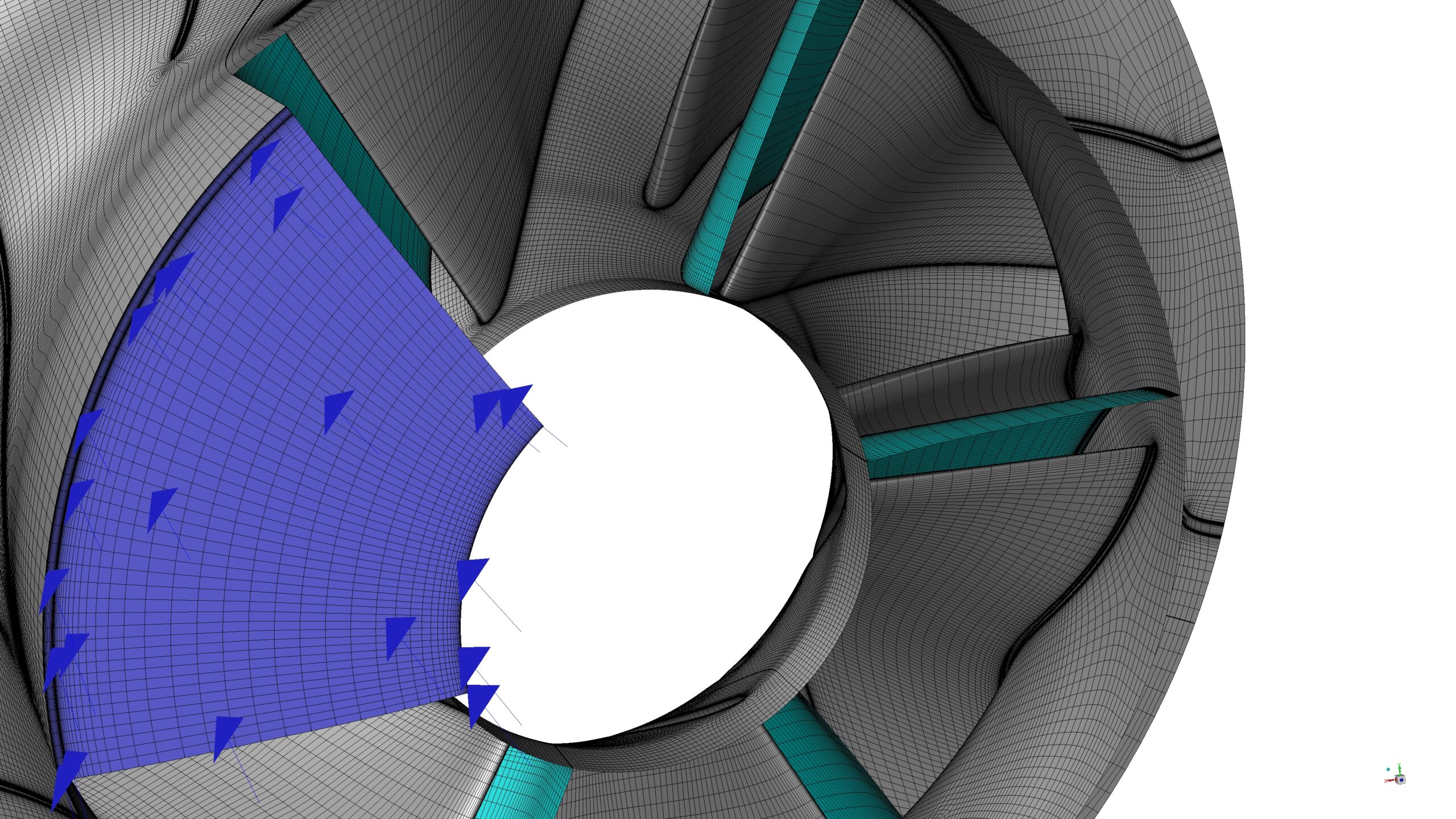
The CFD simulations were conducted using ANSYS Fluent software. The geometry was designed in ANSYS Design Modeler and meshed using ANSYS Meshing software, resulting in a high-quality structured mesh with 961,463 elements.
Methodology
The simulation employs a pressure-based solver, and the air density is considered ideal gas, suitable for compressible flows typically encountered in turbocharger applications.
A steady-state solution approach was adopted to simulate the continuous operation of the turbocharger under constant inlet conditions.
The SST k-ω turbulence model was used to account for the complex flow patterns within the turbocharger.
The energy equation was enabled to track the temperature distribution and heat transfer within the system.
Periodic boundary conditions were applied to model one-sixth of the domain, reducing computational cost while maintaining accuracy.
The Frame Motion model was used to simulate the blades’ rotational movement at 92,000 revolutions per minute, accurately representing the turbocharger’s high-speed operation.
Results
The CFD simulations reveal significant insights into the fluid dynamic and thermal behavior of the turbocharger:
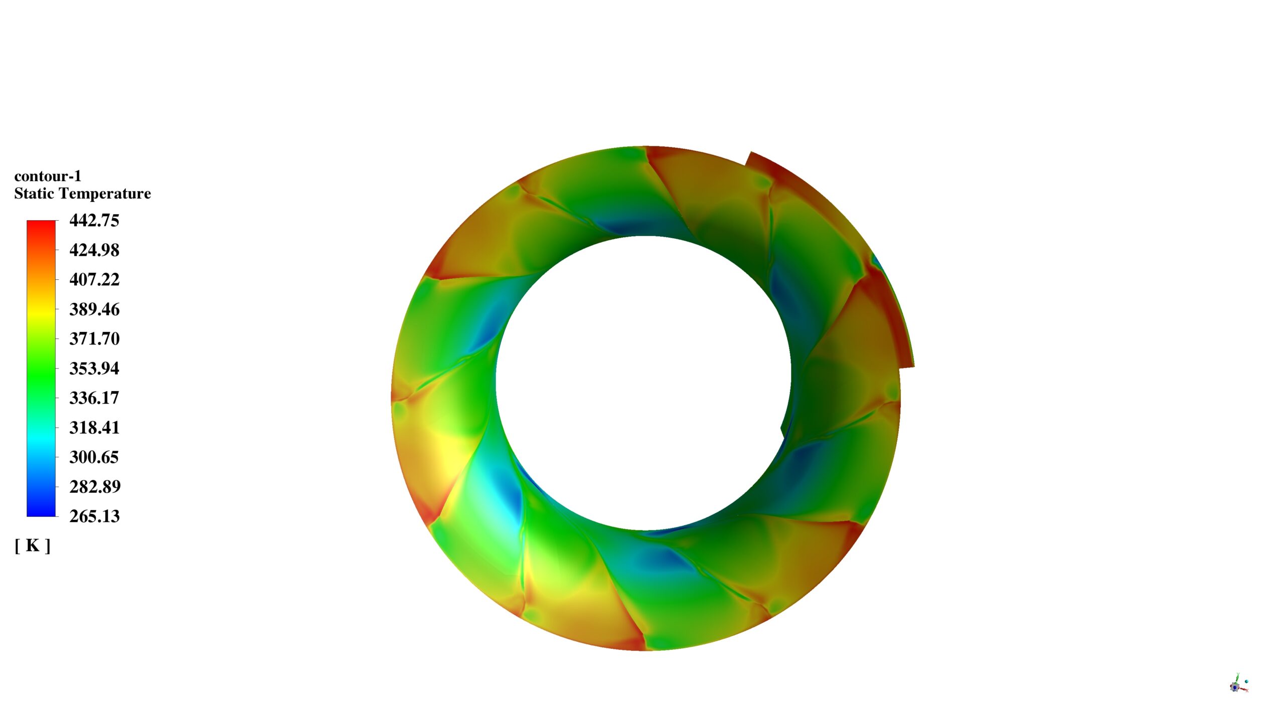
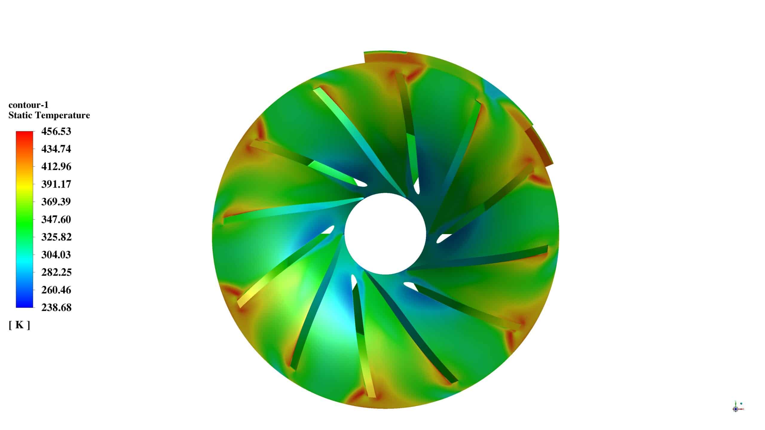
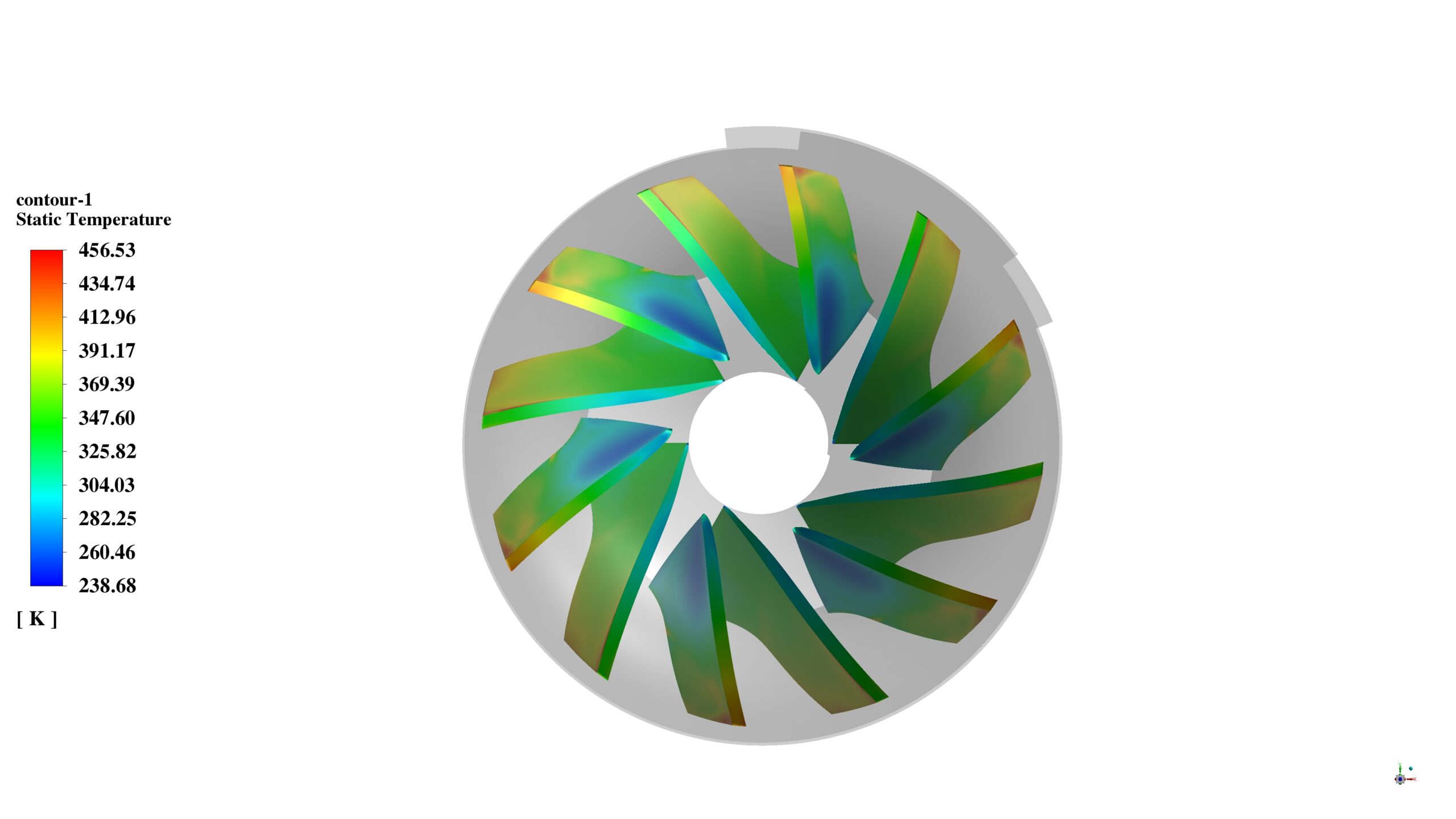
The simulation shows a mass flow rate of 0.025838297 kg/s at the inlet and -0.026005302 kg/s at the outlet, with a net difference of -0.000167005 kg/s, indicating a well-balanced mass flow through the system. Also, the temperature contours show air heating as it passes through the turbocharger. The average static temperature at the outlet is 354.24793 K, demonstrating the turbocharger’s compression effect. The temperature range across the turbocharger is from 349.25 K to 353.05 K, illustrating the device’s temperature rise.
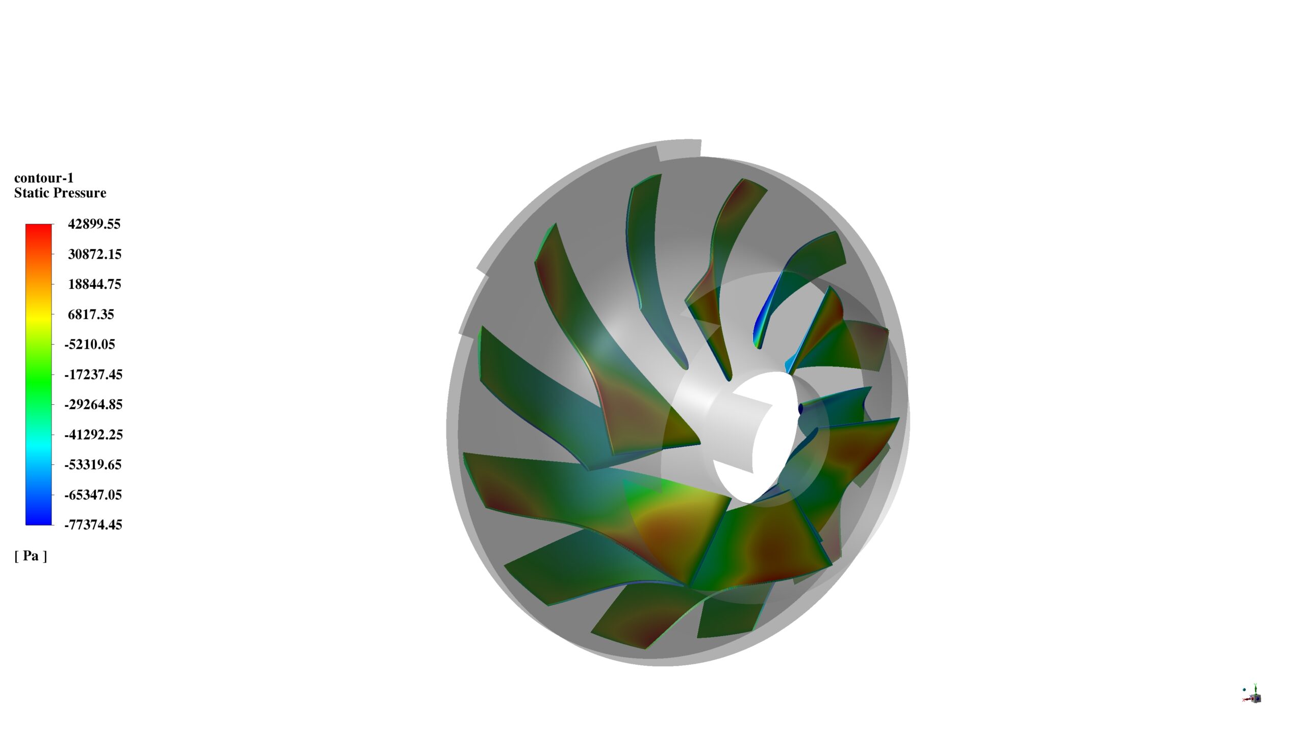
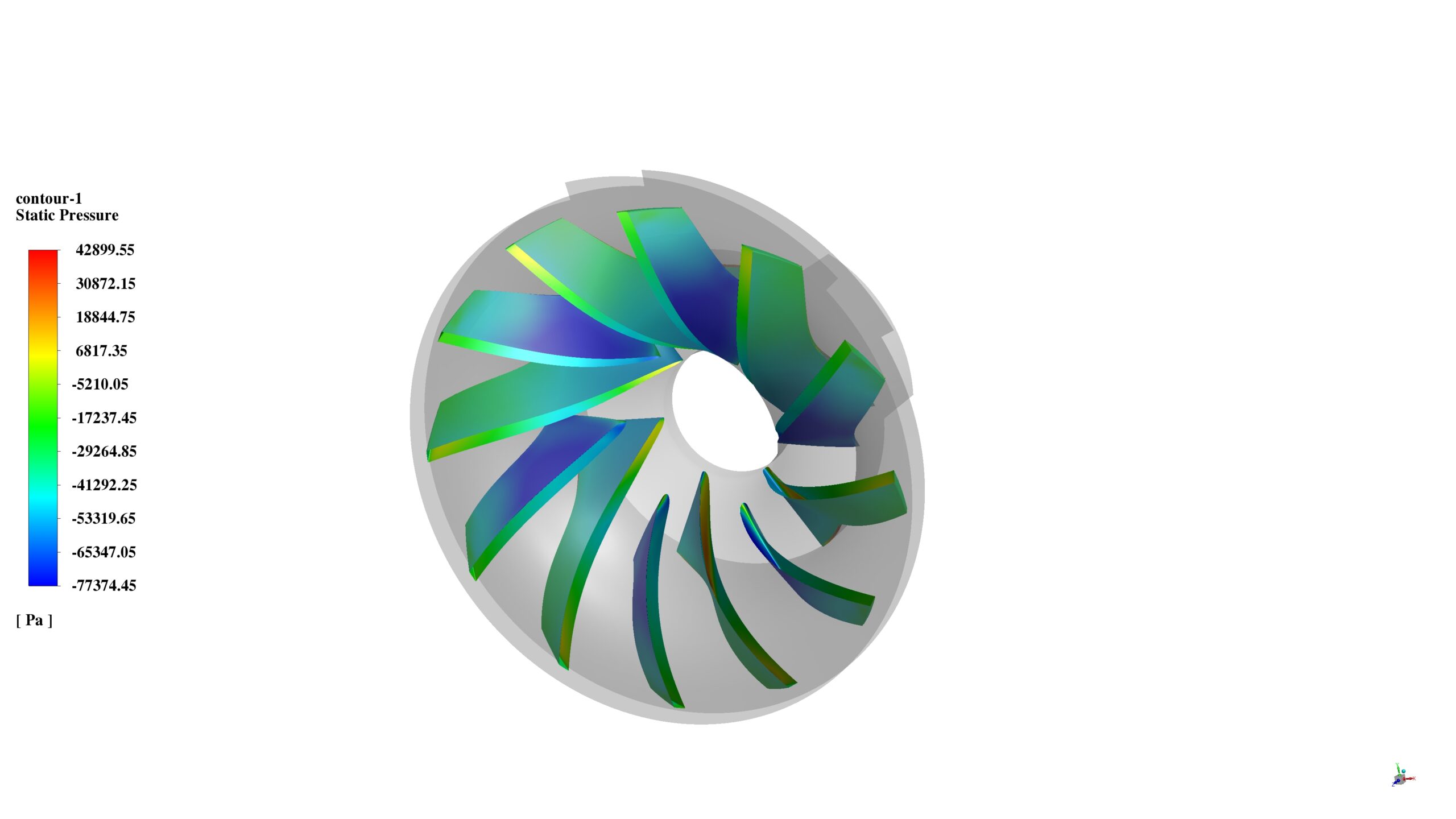
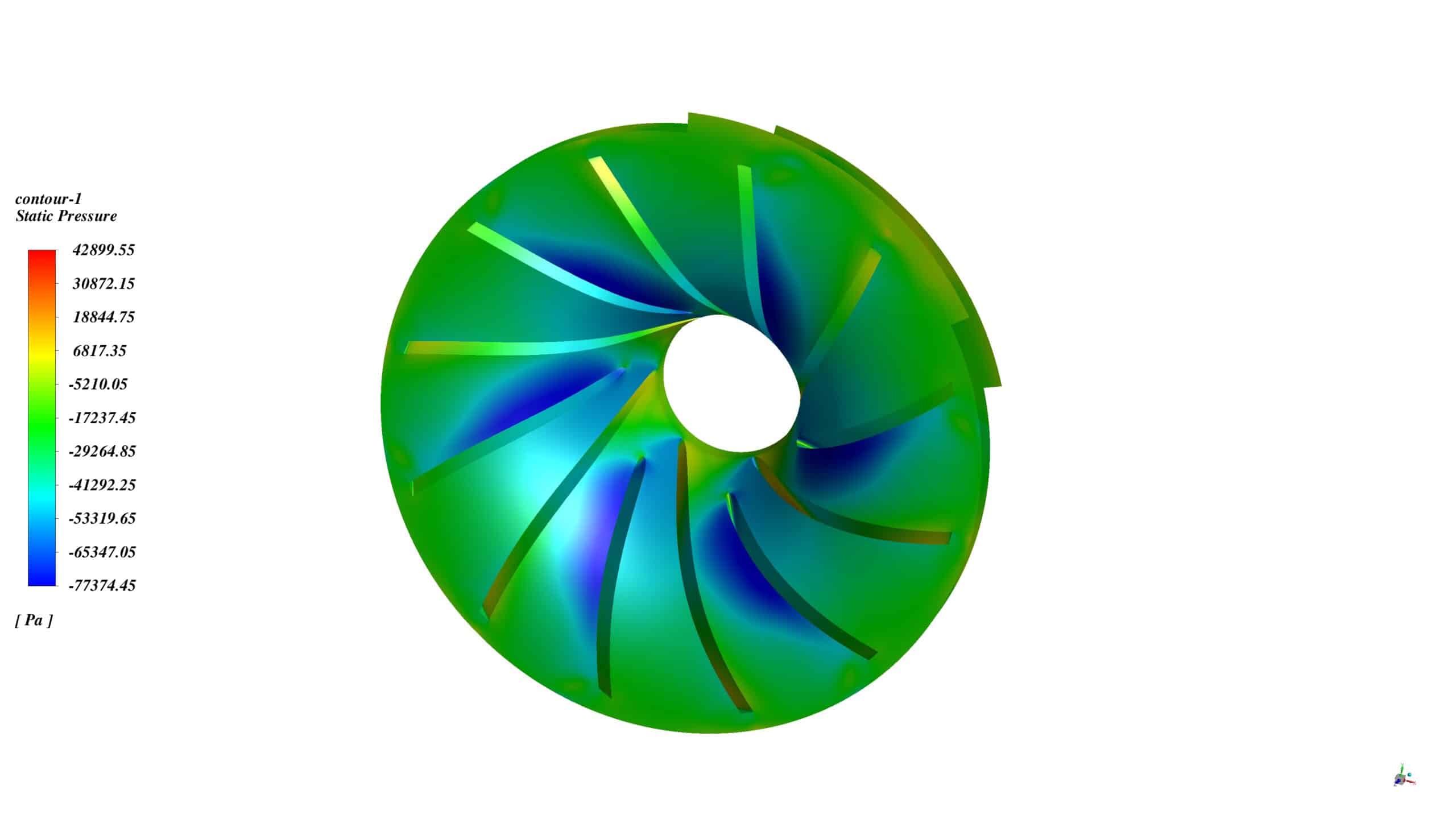
The pressure contours indicate areas of high pressure near the blades and low pressure in the core flow. The pressure range across the turbocharger is from -77374 Pa to 42900 Pa, illustrating the pressure rise achieved by the device.
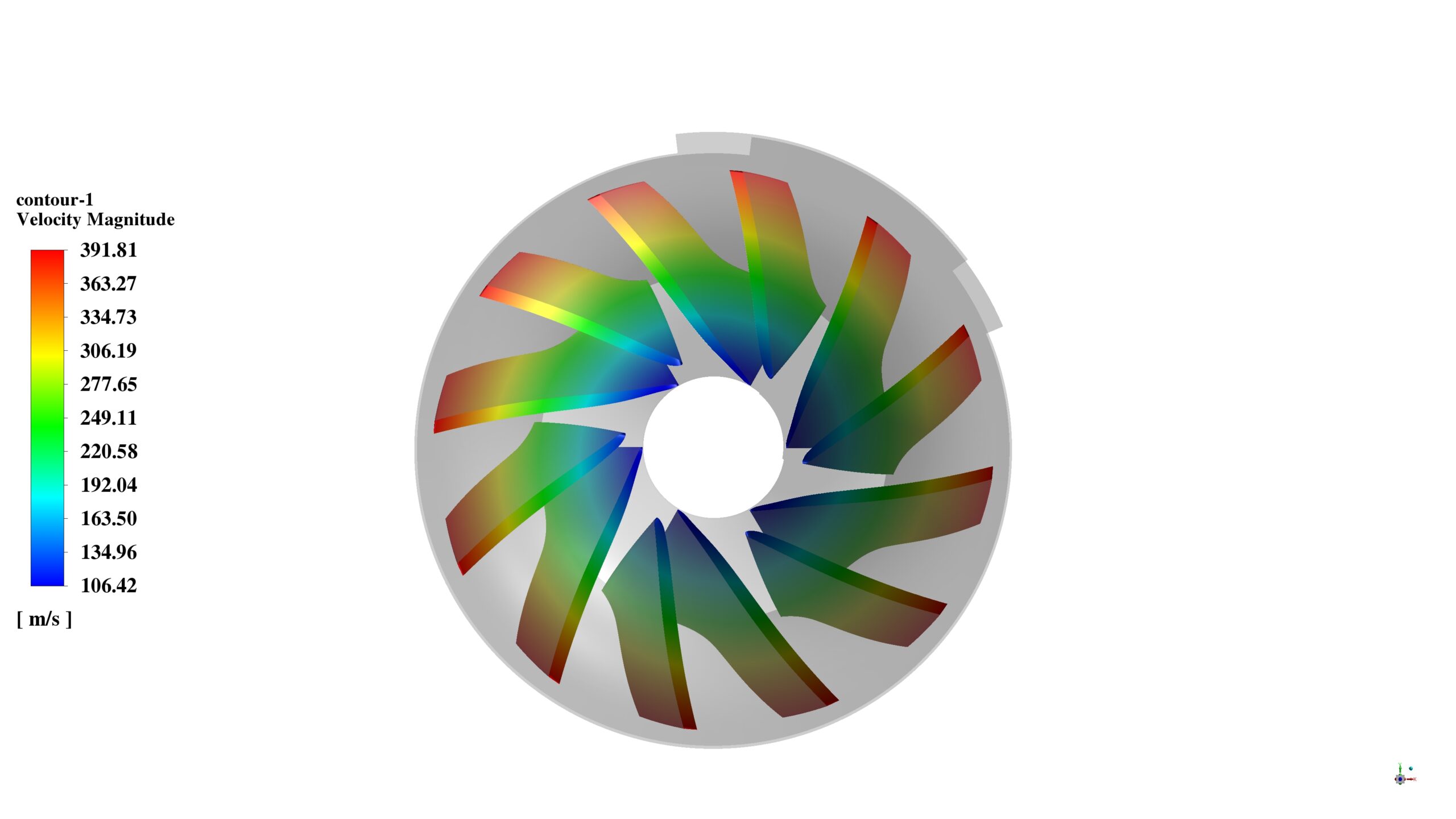
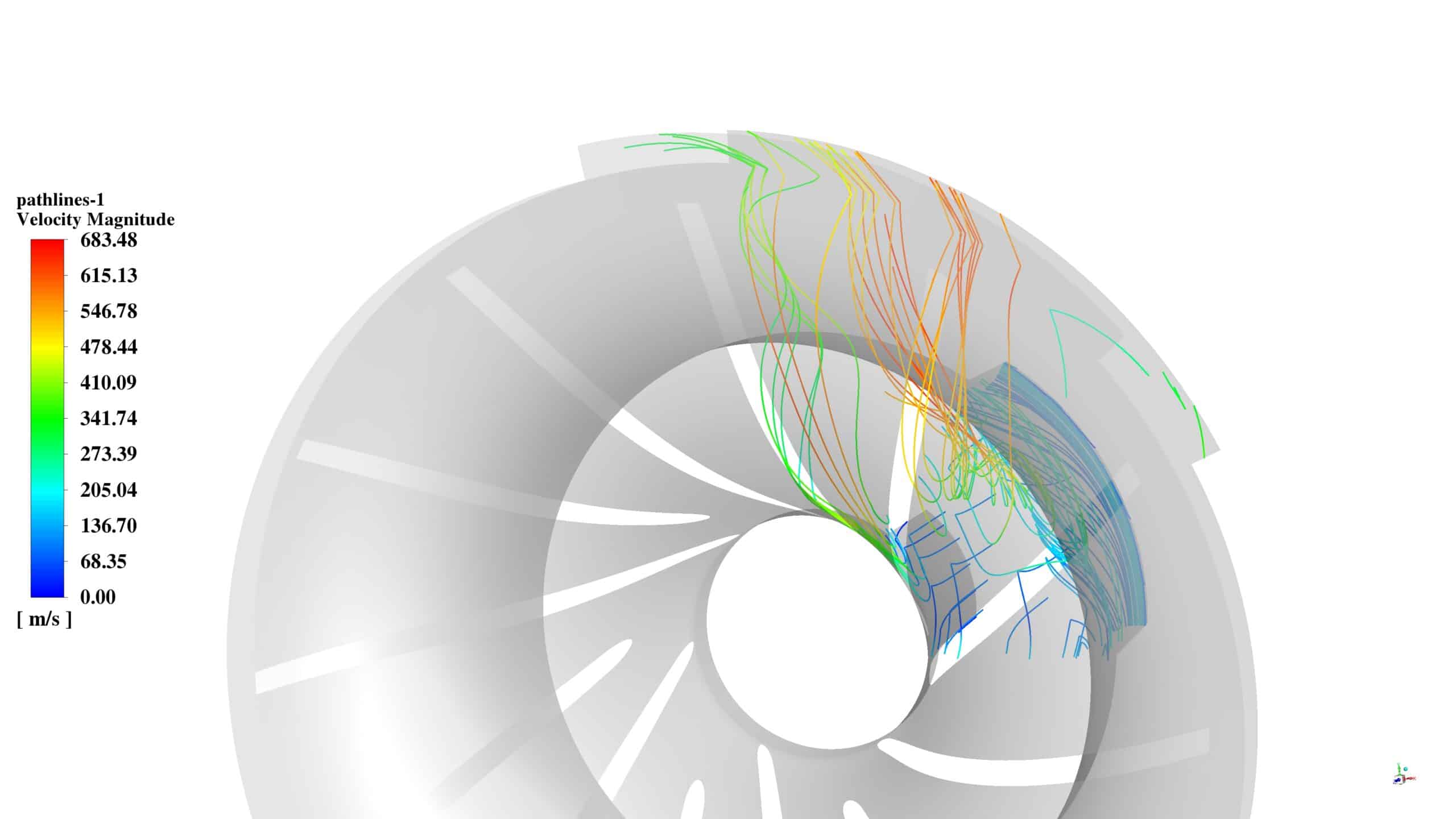
The velocity pathlines and contours show complex flow patterns within the turbocharger. The flow accelerates as it passes through the blade passages, reaching velocities up to 600 m/s. The twisted blade geometry creates a swirling motion, enhancing the compression effect.
The simulation results demonstrate the complex interplay between fluid flow, pressure, and temperature in the turbocharger. The geometry significantly influences the flow patterns, creating regions of high velocity and turbulence, which in turn affect the compression and temperature rise of the air. The heating of the air as it passes through the turbocharger is evident, with the temperature rising from ambient conditions at the inlet to 354.25 K at the outlet.



Reviews
There are no reviews yet.