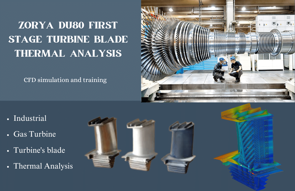
ZORYA DU80 FIRST STAGE TURBINE BLADE THERMAL ANALYSIS
$300.00 $150.00 Student Discount
- Gas turbine engines represent one of the most challenging applications in modern engineering
- The ZORYA DU80 first-stage turbine blade represents a sophisticated integration of aerodynamic design and thermal management.
- The thermal analysis was conducted using ANSYS Discovery,
To Order Your Project or benefit from a CFD consultation, contact our experts via email (info@mr-cfd.com), online support tab, or WhatsApp at +44 7443 197273.
There are some Free Products to check our service quality.
If you want the training video in another language instead of English, ask it via info@mr-cfd.com after you buy the product.
Description
INTRODUCTION
Gas turbine engines represent one of the most challenging applications in modern engineering, operating under extreme thermal and mechanical conditions. The first-stage turbine blades of the ZORYA DU80 gas turbine are critical components that must withstand temperatures exceeding 1200°C while maintaining structural integrity and aerodynamic performance. These components are subjected to severe thermal loads, high-speed rotation, and complex aerodynamic forces. The development of effective cooling strategies is paramount, as operating temperatures frequently surpass the melting point of the blade materials. This study presents a comprehensive thermal analysis of the ZORYA DU80 first-stage turbine blade using advanced computational fluid dynamics (CFD) techniques.
Modern gas turbine development is driven by the pursuit of higher thermal efficiencies, which necessitates increasingly higher turbine inlet temperatures. This creates a fundamental challenge: the operating temperature often exceeds the material’s thermal limits. To address this challenge, sophisticated cooling systems have been developed, incorporating internal cooling passages, film cooling, and thermal barrier coatings. The effectiveness of these cooling systems directly impacts engine performance, reliability, and component lifespan.
BLADE DESIGN AND GEOMETRY
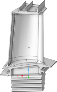
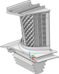
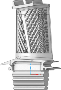
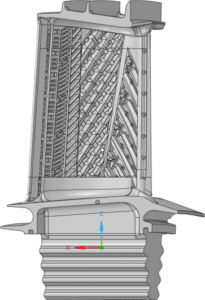
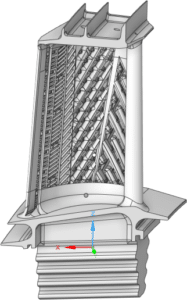
The ZORYA DU80 first-stage turbine blade represents a sophisticated integration of aerodynamic design and thermal management. As illustrated in Figure 1, the blade features an advanced profile with carefully engineered internal cooling passages. The three-dimensional geometry shown in Figure 1(a) demonstrates the complex external profile designed to optimize aerodynamic performance, while Figure 1(b) reveals the intricate internal cooling channel architecture. These cooling passages are arranged in a serpentine pattern, facilitating efficient heat removal from critical areas. The blade’s design incorporates specific features for leading edge cooling, mid-chord cooling, and trailing edge cooling, all working in concert to maintain acceptable metal temperatures under extreme operating conditions.
The key dimensional and operational parameters of the bladed wheel are summarized in Table 1. The blade assembly operates with a mean diameter of 0.882 m at the cascade outlet, with individual blades having a height of 0.062 m. These dimensions were carefully selected to optimize aerodynamic performance while maintaining structural integrity. The blade geometry incorporates sophisticated features including a twisted profile from root to tip to account for varying flow conditions along the blade span. This design approach ensures optimal flow angles and pressure distributions throughout the blade passage.
The cooling system architecture comprises three primary zones: the leading edge, mid-chord, and trailing edge regions. The leading-edge cooling system, visible in Figure 1(c), features an array of impingement cooling holes with diameters ranging from 0.5 to 0.8 mm, strategically positioned to protect the blade from the highest thermal loads. The mid-chord section incorporates a series of serpentine passages with aspect ratios optimized for maximum heat transfer coefficient enhancement. These passages include turbulators and pin fins with heights of 1.2-1.5 mm, spaced at intervals of 8-10 mm to promote turbulent mixing and improve cooling effectiveness.
The trailing edge region employs a combination of pedestals and ejection slots, with pedestal diameters of 1.0-1.2 mm arranged in a staggered pattern to maintain structural integrity while facilitating effective cooling. The internal cooling channels maintain a cross-sectional area ratio of 1.2:1 from inlet to outlet to compensate for density changes as the cooling air heats up. Trip strips with a height-to-channel hydraulic diameter ratio of 0.1 are incorporated along the internal passages to enhance heat transfer coefficients by up to 2.5 times compared to smooth channels.
Working under the operating conditions detailed in Table 1, including high stagnation temperatures and significant pressure gradients, the blade design must balance multiple competing requirements. The total cooling flow is distributed with approximately 40% directed to the leading edge, 35% to the mid-chord region, and 25% to the trailing edge section. This distribution is optimized based on thermal load analysis and verified through extensive CFD simulations. The geometry optimization considers not only thermal and aerodynamic performance but also manufacturing constraints and material limitations. The wall thickness varies from 2.5 mm at the leading edge to 1.8 mm at the trailing edge, maintaining structural integrity while facilitating effective heat transfer.
This integrated design approach ensures that the blade can effectively handle extreme conditions while maintaining optimal performance characteristics throughout its operational life. The cooling effectiveness, defined as (Tg – Tw)/(Tg – Tc), ranges from 0.4 at the leading edge to 0.6 in the mid-chord region, where Tg is the gas temperature, Tw is the wall temperature, and Tc is the coolant temperature.
Table 1: Bladed Wheel Specifications and Operating Parameters
|
Parameter Description |
Value |
| Mean diameter at cascade outlet |
0.882 m |
| Blade height at cascade outlet |
0.062 m |
 |
 |
|
a |
b |
 |
 |
|
c |
d |
 |
 |
| e |
f |
Figure1: Geometry
COMPUTATIONAL ANALYSIS SETUP
The thermal analysis was conducted using ANSYS Discovery, employing a comprehensive approach to simulate the complex thermodynamic interactions within the turbine blade. The simulation utilized a high-fidelity model incorporating Inconel 718, a nickel-based superalloy specifically chosen for its exceptional high-temperature performance characteristics. This material exhibits optimal properties with a density of 8000 kg/m³, specific heat capacity of 456 J/Kg*K, and thermal conductivity ranging from 554 to 75.5 W/m*K across the operational temperature range. The model implements a sophisticated multi-physics approach, combining fluid dynamics with heat transfer analysis to accurately predict temperature distributions and thermal gradients.
The simulation boundary conditions were carefully defined to reflect real operating conditions, with the main gas path temperature set at 1241.1°C and inlet total pressure at 1.3137 MPa. The cooling system operates with air at 470.5°C, delivered at a flow rate of 7.41 kg/s through strategically positioned cooling channels. Three distinct flow inlets were modeled to accurately represent the cooling system: primary and secondary cooling flows at 2.15e6 Pa and 470°C, and the hot gas path at 7.75e5 Pa and 1243°C. The outlet condition was maintained at 3.89e5 Pa to ensure proper flow development through the blade passages. This comprehensive setup enables accurate prediction of temperature distributions, thermal stresses, and cooling effectiveness throughout the blade structure.
RESULTS AND DISCUSSION
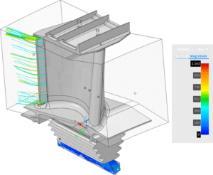
Thermal Distribution Analysis (Figure 2) The thermal analysis results reveal intricate temperature distribution patterns across the ZORYA DU80 first-stage turbine blade. Figure 2 presents comprehensive temperature contours from the CFD analysis, demonstrating temperature variations from 410K to 1250K (137°C to 977°C). The leading-edge region, as shown by the red zones in Figure 2(a), experiences the highest thermal loading with temperatures approaching 1250K due to direct hot gas impingement. The effectiveness of the cooling system is particularly evident in the mid-span region, where the internal cooling channels maintain temperatures between 600-800K, represented by the green zones in Figure 2(b). The blade tip region shows a distinct thermal gradient pattern, with temperatures gradually increasing from root to tip, indicating the combined effects of rotational forces and cooling effectiveness reduction along the span.
Flow Field Characteristics (Figure 3) The velocity contour analysis presented in Figure 3 reveals complex aerodynamic behavior across the blade passage. At the cascade outlet, the flow achieves a relative velocity of 573.8 m/s, with axial and circumferential components of 225.0 m/s and 91.4 m/s respectively. Figure 3(a) illustrates the acceleration of flow along the suction surface, with peak velocities occurring at approximately 70% of the axial chord. The boundary layer development, visible in Figure 3(b), shows no significant flow separation, indicating optimal aerodynamic design. The velocity distribution near the cooling hole exits, highlighted in Figure 3(c), demonstrates effective mixing between the coolant and mainstream flows, with local velocity ratios (coolant to mainstream) maintained between 0.6-0.8 for optimal cooling performance.
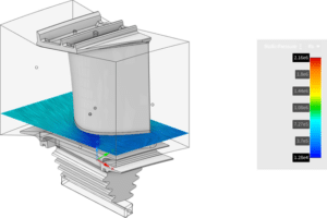
Pressure Distribution Analysis (Figure 4) The pressure contours displayed in Figure 4 demonstrate the complex pressure field across the blade surface. Figure 4(a) shows the pressure gradient from inlet (1.3137 MPa) to outlet (0.7263 MPa), with distinct high-pressure regions on the pressure surface and low-pressure zones on the suction surface. The pressure distribution along the span, illustrated in Figure 4(b), reveals a consistent pattern of loading, essential for aerodynamic stability. Of particular interest is the pressure field around the cooling hole exits (Figure 4(c)), where local pressure gradients ensure proper coolant distribution without flow reversal.
Flow Path Visualization (Figure 5) The streamline analysis presented in Figure 5 provides crucial insights into the three-dimensional flow behavior. Figure 5(a) shows the primary flow path through the blade passage, with streamlines colored by velocity magnitude. The secondary flow patterns, visible in Figure 5(b), indicate the presence of passage vortices near the endwalls, with their strength diminishing toward mid-span. The interaction between cooling jets and mainstream flow, depicted in Figure 5(c), demonstrates effective mixing patterns that enhance overall cooling effectiveness while minimizing aerodynamic losses.
 |
 |
|
a |
b |
 |
 |
|
c |
d |
Figure2: Temperature contour
Figure3: Velocity contour
Figure4: Pressure contour
 |
 |
|
a |
b |
Figure5: Streamlines
CONCLUSION
Based on the comprehensive thermal analysis of the ZORYA DU80 first-stage turbine blade, several significant conclusions can be drawn. The CFD simulations, conducted using ANSYS Discovery, demonstrate the effectiveness of the blade’s cooling system design, as evidenced by the temperature distribution patterns shown in the thermal contour plots. The analysis confirms that despite exposure to inlet temperatures of 1363K (1090°C), the cooling system successfully maintains blade temperatures within acceptable operational limits, with temperature variations from 410K to 1250K across different regions of the blade.
The aerodynamic performance parameters, including the flow velocity of 573.8 m/s at the blade outlet and the pressure drop from 1.3137 MPa to 0.7263 MPa, indicate efficient energy extraction through the turbine stage. The sophisticated cooling design, incorporating multiple flow inlets at 470°C and 2.15e6 Pa, effectively manages the thermal loads while maintaining structural integrity. The thermal visualization results, particularly evident in the provided temperature contour images, show effective cooling in the blade’s internal passages, with the serpentine cooling channels successfully reducing temperatures in critical areas.
The study validates that the current blade design and cooling configuration meet the demanding requirements of modern gas turbine operation. The implementation of Inconel 718 with its specific material properties, combined with the strategic placement of cooling channels, provides an optimal balance between thermal management and aerodynamic performance. These findings contribute valuable insights for future turbine blade designs and cooling system optimizations, particularly in applications requiring high-temperature operation and maximum thermal efficiency.





Reviews
There are no reviews yet.